
Subscribe to Our Youtube Channel
Related Manuals for GE WCCB1030WYC


Summary of Contents for GE WCCB1030WYC
- Page 1 GE Consumer Service Training TECHNICAL SERVICE GUIDE GE Coin-Operated Washers Fill MODEL SERIES WCCB1030WYC WCCB1030YAC WCCD1030YWC WCCD1030YAC WLCD1030YWC WLCD1030YAC WCCD2050YWC WCCD2050YAC WLCD2050YWC WLCD2050YAC Pub # 31-9036 10/99...
-
Page 2: Table Of Contents
Table of Contents Rating Plate/Mini Manual Countback Backsplash Specifications/Features Dimensions/Water Usage Installation Instructions Filter/Agitator Control Panel Service Timer Cabinet/Front Panel/Cover-Lid Economy Water Usage Suspension Spin Basket Removal Tub/Motor Assembly Service Remote Pump, Motor/Clutch Clutch Removal/Belt Tension Transmission Service 20-21 22-23 Schematic 24-34 Exploded Views/Parts... -
Page 3: Rating Plate/Mini Manual
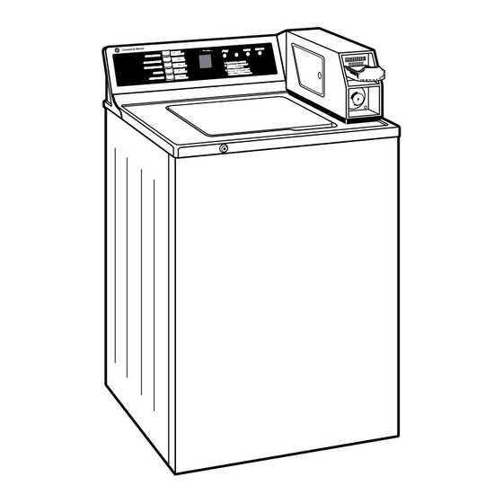
Rating Plate and Mini-Manual Location The rating plate containing model and serial number is located on the rear of the control panel in the center. If you lean over the washer you can see the rating plate without moving the unit. Rating Plate at rear of backsplash... -
Page 4: Countback Backsplash
OPERATING RINSING FINAL SPIN (ADD FABRIC SOFTENER) COTTONS WHITE HOT WASH Commercial Washer COTTONS COLOR WARM WASH See instructions under lid. & REGULAR PERM PRESS Add fabric softener just after DELICATE PERM PRESS RINSE light comes on. COLD WASH & MIXED LOADS For your safety, washer won’t run with lid open. -
Page 5: Specifications/Features
. r e • Tamper Resistant Lid switch Minimizes vandalized lid switches • Plus Debit Card Capability Accessory kit designed exclusively for GE... -
Page 6: Dimensions/Water Usage
Dimensions/Water Consumption Energy Saving All wash cycles include energy-saving cold water rinse. Connector in backsplash can be joined for warm rinse. Total cycle time --- 29 minutes plus fill time. Actual wash time is 11 minutes with final spin speed of approximately 630 RPM. -
Page 7: Installation Instructions
Installation Instructions... -
Page 11: Filter/Agitator
Lint Removal System The lint filtering system consist of the turbo pump, agitator, air bell, and self cleaning filter at bottom of spin basket. During agitate water moves throught the sides and up from the bottom throught the self cleaning filters. During pump down, prior to spin, the turbo pump is energized, and water is drawn out the sides and down through the self cleaning filter to clean and... -
Page 12: Control Panel Service
Control Panel The control panel is designed with ease of service being the major consideration. The switches are tab interlock, and harness connectors are designed to only fit the correct mating connector. Control panel is galvanized, with three tabs designed to al- low the switchtrim to be supported during service. -
Page 13: Timer
Timer cam charts and schematics are shown in this manual. °Accessory kit with debit card capability is available and designed exclusively for GE NOTE: Lid switch can be accessed by removing door and latch assembly on meter case as shown in illustration. -
Page 14: Cabinet/Front Panel/Cover-Lid
Cabinet Cabinet is galvanized sheet metal, with powdered paint coating and is rust resistant. It has a fully en- LOCATE SPRING CLIPS closed bottom, and is 3 sided with a front panel. ON EITHER The lid has a patented colored lid instruction that is SIDE AND RELEASE unique to each model. -
Page 15: Economy Water Usage
Water Pressure Switch WARM RINSE OPTION CONNECTORS MINI- MANUAL The water pressure switch is a new design and is accurate. Rotating the dial sets a cam that controls the diaphragm, the water pressure is sensed through pressure from the take off at the lower por- tion of the tub.Terminal connectors are marked (NC) and (NO) normally open, and common terminal on the switch. -
Page 16: Suspension
Suspension The suspension system is unique in that the spin basket, tub, and leg and platform assembly are sus- pended for the rod support. The rod support sets atop the cabinet and provides, through 4 socket lin- ers durable ball joints. The rod support gives the suspension a pivot point for the rod and spring as- sembly. -
Page 17: Spin Basket Removal
SPIN BASKET (4) 5/16" DAMPENER To Service Spin Basket DAMPENER SCREWS SCREWS 1. Remove front panel and cover/lid. 2. Disconnect (4) dampening straps from tub, at- tached by 5/16" hex head screws. 3. Remove tub cover by lifting out 8 tabs on tub cover, and pulling cover off. -
Page 18: Tub/Motor Assembly Service
TUB/MOTOR ASSEMBLY PULL TOP OUT FRONT To Service Tub/Motor Assembly 1. Remove front panel, cover/lid, remove agitator by using belt tool, insert under agitator and pull up sharply. 2. Remove split ring and washer from transmission. 3. Remove front rod and spring asm. (one at a time) by lifting motor tub assembly up to take weight off suspension bellows at lower portion of the rod. -
Page 19: Remote Pump, Motor/Clutch
PUMP To Service Tub Seal 1. Remove basket as previously shown. 2. Using channel locks, grasp 1 of the four tabs molded into the top of the seal, and pull the seal out. 3. Position new seal and seat, tap or push the seal into place, making sure seal is fully seated. -
Page 20: Clutch Removal/Belt Tension
Clutch To Remove Clutch: Clutch can be ordered as a repair part, and is not shipped with the motor. A common clutch is used for both single and two speed motors. 1. Remove non reusable sping clip by grasping clip with pliers, as shown in illustration, and rotate to remove. -
Page 21: Transmission Service
Transmission To Service Transmission: 1. with motor/tub/transmission assembly upside down, loosen motor mounts to release belt tension. 2. Remove transmission drive pulley by holding belt to- gether as shown. Remove pulley nut. (1 3/4”) 3. After pulley is removed, remove (4) 3/8” bolts mount- ing the transmission mounting plate to leg and platform assembly. - Page 22 Transmission (con’t.) NOTE: Transmission cutaway view below is shown to provide you with a glimpse of the internal work- ings of this rotating transmission. It features all metal gears, metal counterweight, and 5.5 oz. of oil. The transmission and quiet brake are one compo- nent, and is replaced and not rebuilt.
-
Page 23: Schematic
SCHEMATIC CAUTION: TO SERVICE MACHINE, POWER MUST BE DIS- CONNECTED NOTE: This schematic is a full featured model, and the schematic/cam charts do not cover all models. For your particular models. See the instructions on page 3 on access- ing the Mini- Manual, located in every washer backsplash, with up to date information on servicing that washer. - Page 24 SCHEMATIC...
-
Page 25: Exploded Views/Parts
MODELS: WCCD1030YOAC WCCD1030YOWC WLCD1030YOAC WLCD1030YOWC NOTE: Part #110 “BOARD COIN-OP” & Part #120 “PcB Cover COIN-OP” are shipped as one (1) part. - Page 26 MODELS: WCCB1030YOAC WCCB1030YOWC...
- Page 27 MODELS: WCCD2050YOAC WCCD2050YOWC WLCD2050YOAC WLCD2050YOWC NOTE: Part #110 “BOARD COIN-OP” & Part #120 “PcB Cover COIN-OP” are shipped as one (1) part.
Need help?
Do you have a question about the WCCB1030WYC and is the answer not in the manual?
Questions and answers