Table of Contents
Advertisement
F
Y
EI
U
T
ECH
Guilin Feiyu Electronic Technology Co., Ltd
Rm. B305, Innovation Building, Information Industry Park, Chaoyang Road, Qixing District,
GuiLin, CN
www.fyetech.com
Email: fyetech@yahoo.com
FY-41AP A
Airplane flight stabilization & Autopilot System
Installation & Operation Guide
UTOPILOT
Rev: (0) April 16 2013
S
YSTEM
Advertisement
Table of Contents

Related Manuals for FeiYu Tech FY-41AP


Summary of Contents for FeiYu Tech FY-41AP
- Page 1 Rev: (0) April 16 2013 FY-41AP A UTOPILOT YSTEM Airplane flight stabilization & Autopilot System Installation & Operation Guide Guilin Feiyu Electronic Technology Co., Ltd Rm. B305, Innovation Building, Information Industry Park, Chaoyang Road, Qixing District, GuiLin, CN www.fyetech.com Email: fyetech@yahoo.com...
-
Page 2: Table Of Contents
FY-41AP Standard Configuration ..............6 Optional Accessory ..................6 FY41AP Specification & Working Requirement ............ 7 The FY-41AP Aircraft Configuration Options ............7 The FY-41AP RC System Compatibility .............. 7 FY-41AP Connection Interface ................8 VIEW A Interface Diagram:................8 VIEW B Interface Diagram ................ - Page 3 Max Distance Setting ................. 36 Cruising Speed Setting ................36 Air Speed Sensor ..................36 FY-41AP FIRST FLIGHT TEST CHECKLIST ............39 Data Radio & Gcs Software ................40 Warning: Pilot Input And Autonomous Flight Interaction ........42 Fail-Safe And Autonomous Return To Lauch ............. 43 FY-41AP-OSD INSTRUCTIONS ...............
- Page 4 If you are already an experienced flyer, you will find the FY-41AP installation to be easy & logical. Follow this manual & you won‟t go wrong. If you need further technical support, contact us at: service@feiyu-tech.com...
- Page 5 Fyetech Electronics Technology d) GPS Data – enables the FY-41AP to calculate the flight course & sense the exact location of the aircraft. GPS Data allows aircraft return to home (RTL), Auto Circle, Fixed altitude, Heading lock flight and fully autonomous flight via GPS waypoints setting.
-
Page 6: Fy-41Ap Flight Modes
FY-41AP FLIGHT MODES With GPS data input, the following are the FY41AP selectable flight modes: ● Deactivated Mode - In this mode, the FY-41AP auto stabilization is turned off. The aircraft is completely under pilot control. ● Stabilized Mode - level flight is automatically maintained, making flight simple, especially for beginners. -
Page 7: Fy-41Ap Standard Configuration
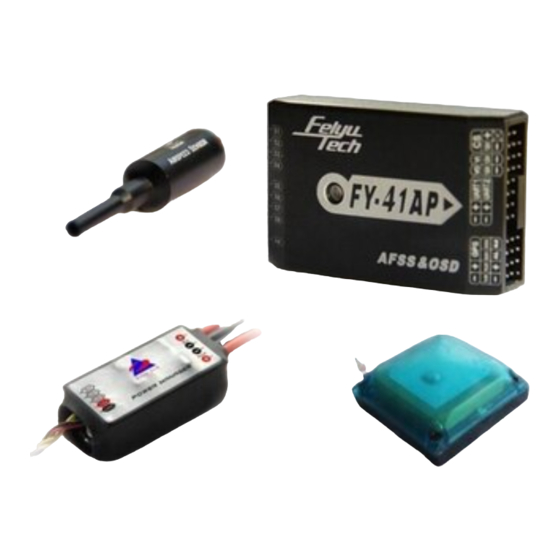
Fyetech Electronics Technology FY-41AP STANDARD CONFIGURATION FY-41AP Control Module Power Management Module Airspeed Sensor RC receiver connecting wires USB cable GPS module 4P Y cable Velcro tape and damper pads Optional accessory Data Radio Remote Adaptor Page | 6... -
Page 8: Fy41Ap Specification & Working Requirement
Any other configuration please consult us: service@feiyu-tech.com The FY-41AP has been tested to work with the following RC systems ● Robbe-Futaba PPM / PCM 1024 / PCM G3 mode, 2.4 GHz systems; ● Graupner/JR PPM 8, PPM 12, SPCM mode;... -
Page 9: Fy-41Ap Connection Interface
Fyetech Electronics Technology FY-41AP CONNECTION INTERFACE LED Indicator View A View B VIEW A Interface diagram: AIL2 Servo Power Power Power Power Power Power Power Power Output Interface A) The Yellow pins S1 ~ S8 are signal output to aircraft servos. -
Page 10: View B Interface Diagram
Fyetech Electronics Technology S7:When use Remote Adaptor, this pin outputs RC receiver CH7 (refer Remote Adaptor & Data Radio Manual) S8:When use Remote Adaptor, this pin outputs RC receiver CH8 (refer Remote Adaptor & Data Radio Manual) B) The middle pins of View A are (+ve) power output to aircraft servos. Important Note: Power is supplied from the RC Receiver. -
Page 11: Connecting The Fy41Ap To The Rc Receiver
4 Receiver channels are used for aileron (Ch 1), elevator (Ch 2), throttle (Ch 3) & rudder (Ch 4). 2 free Receiver channels are required to control the FY-41AP Flight Modes via SW1 & Navigation Mode via SW2. Page | 10... - Page 12 Fyetech Electronics Technology c) UART1 module interface: UART1-TXD UART1-RXD This port is used to: Connect to your PC via supplied USB cable to update the FY41AP autopilot firmware. Connects to FY Data Radio for communication via FY-GCS a) UART1-TXD :...
- Page 13 Fyetech Electronics Technology e) Video Signal In/Out interface: V-out V-in V-out:connect to video transmitter V-in: connect to FPV Camera video output 12V: 12 Volt output supply to video transmitter and camera (make sure your equipment is rated 12 volts!) GND:connect to video transmitter or camera –ve. e) CS (Current Sensor) interface:...
-
Page 14: Plane Servo Connection (Refer View A)
Fyetech Electronics Technology PLANE SERVO CONNECTION (Refer VIEW A) 1) Connection for traditional Aileron/Elevator/Rudder airplane layout: Aileron Elevator ESC/throttle Rudder Aileron servo 1 servo servo servo servo 2 2) Connection for flying wing aircraft (with or without Rudder) Differential Differential ESC/throttle Rudder Servo 1... -
Page 15: Integrated Current Sensor / Power Manager
Fyetech Electronics Technology INTEGRATED CURRENT SENSOR / POWER MANAGER a) The FY-41AP is supplied with a Power Manager that is both a current sensor & supply. b) The module outputs +5v to supply to the FY41AP and RC Receiver. It also supplies regulated +12v to power the video transmitter and FPV camera. - Page 16 Fyetech Electronics Technology NOTE: The Power Manager is NOT rated to supply power to the airplane servos. To power the servos, use your ESC BEC connected via VIEW A interface of the FY41AP. We highly recommend to use a +5v to +6v External BEC (rated for 3A output) plugged through VIEW A interface.
-
Page 17: Gps Installation And Requirements
Fyetech Electronics Technology GPS INSTALLATION AND REQUIREMENTS a) Install the GPS Module on the airplane with the antenna face up: Face Upwards b) DO NOT install next to metal or carbon fiber & other shielding material, which may block satellite signal reception. c) Install the GPS Module away from electromagnetic sources such as ESC‟s, power wires, servo wires &... -
Page 18: Fy41Ap Connection Summary
Fyetech Electronics Technology FY41AP CONNECTION SUMMARY Page | 17... -
Page 19: Fy-41Ap Led Instruction
Fyetech Electronics Technology FY-41AP LED instruction a) FY-41AP outputs 3 LED colors to indicate flight modes: red, blue and green. b) It also outputs white for Gyro resetting. c) Examples of LED flashing indication: green LED flash means GPS location has been fixed (>4 satellites) ... -
Page 20: Vibration Damping
& gas/nitro powered planes. c) The algorithm in the FY-41AP compensates for normal levels of flight vibration. However, if the vibration exceeds the acceptable level, stabilization will not work normally or may even stop working altogether. -
Page 21: Checking For Vibration Levels
Fyetech Electronics Technology CHECKING FOR VIBRATION LEVELS Even with the shock absorbing mount, your aircraft set up may not meet the vibration damping requirement. To check for vibration level, please follow this procedure: Installing the entire system as recommended (ensure correct orientation). -
Page 22: Switch Channel Setting
3d Mode SW2 DEFAULT SETTING STATE Position servo signal 900~1200US 1200~1800US 1800~2100US output fixed altitude & Auto Return To NULL Function heading lock mode Launch Mode Other function can be set to the SW2 via FY-41AP setting software. Page | 21... -
Page 23: Fy-41Ap Installation Orientation
Fyetech Electronics Technology FY-41AP INSTALLATION ORIENTATION a) FY-41AP support 4 installation orientations (LOGO arrow to up, down left or right). Default installation orientation is logo up with arrow pointing forward (direction of flight) as shown below: b) If the default orientation is not possible, you can change the orientation... -
Page 24: Fy-41Ap Installation Position
Fyetech Electronics Technology FY-41AP INSTALLATION POSITION a) When installing the FY41AP, please install it horizontal & as close as possible to the "Centre of gravity" (COG) of the aircraft. b) A module that is not installed horizontal can result in stabilization issues as... -
Page 25: Setting Correct Servo Direction
Fyetech Electronics Technology SETTING CORRECT SERVO DIRECTION a) After FY41AP, servos, RC Receiver & ESC / Motor installation, it is time to test the control surfaces movement and ESC function. b) Power up the system and check that the servo direction (ailerons, elevator, rudder, differential servo, ESC / Motor function, etc.) using your RC Transmitter. - Page 26 Fyetech Electronics Technology If the servo movement is incorrect, you need to reverse the automated servo movement via the FY41AP software setting. Refer ‘Reversing Servo in Stabilized Mode’ in this Manual. Reversing the servo movement can also be done via your OSD downlink.
- Page 27 Fyetech Electronics Technology e) Observe Automated RUDDER movement ● Rotate the plane as shown below: CLOCKWISE rotate your plane & the rudder should move to the Left. COUNTER CLOCKWISE rotation & the rudder should move to the Right ...
-
Page 28: Gyroscope Reset
(1) The device has not been used for a long time. (2) There is a change in environmental temperature of over 30 degrees since last flight. (3) The purple LED flashes continuously even when the FY-41AP remains stationary & motor not activated. Note:... -
Page 29: Fy-41Ap Setting Software
Fyetech Electronics Technology FY-41AP SETTING SOFTWARE a) The Setting software is used to adjust the FY41AP parameters and module set-up in a simple and fast manner. b) Before conducting this procedure, please ensure you download the required software onto your computer: (1) USB-TTL device driver. - Page 30 Fyetech Electronics Technology If you are powering the FY41AP via your battery pack please make sure you remover the Red Wire from the USB TTL Plug, as shown below: Remove wire if using the FY41AP on board power. Failure to do this may result in damage of your PC and FY41AP.
-
Page 31: (10) Changing Stabilization Gain
Fyetech Electronics Technology Press the „Read ALL‟ button: After making your setting changes, remember to press the „Save‟ button to update the FY41AP flash memory. (10) CHANGING STABILIZATION GAIN: Each channel (Aileron, Elevator, Throttle, Rudder) gain can be adjusted individually. - Page 32 This function is used to eliminate any installation deviation from the default „0‟ (zero) horizontal angle. A non horizontal level can cause Auto Balance Mode flight deviation (Refer FY-41AP INSTALLATION POSITION in this manual). There are two methods to Record horizontal Attitude.
-
Page 33: Install Setting
● FY-41AP supports four installation direction. However, the LOGO must be installed facing up. ● FY-41AP has an arrow printed on the top of it. Normally, this arrow points towards the front (direction of flight). ● If you install the module in any other direction then default forward, you need to set the module direction via the Install Setting option. -
Page 34: Mix Setting
Fyetech Electronics Technology (14) MIX SETTING Selects aircraft configuration. Supports configurations as listed: (ii) NOTE: Your RC Radio transmitter MUST select traditional airplane configuration with No Mixing in any of the channels. If any channel is mixed the FY41AP cannot function normally. Elevon Normal V tail... -
Page 35: Switch Mode" Sw-2 Function Setting
Traditional aircraft The rudder servo must be connected to 1. Normal layout with no Aileron FY-41AP aileron servo output (AIL) V-tail servo has to connect to FY41AP V-tail without aileron 2. Elevons Differential Servo 1 & 2 output. -
Page 36: (16) Reverse - Reversing Servo In Stabilized Mode
Fyetech Electronics Technology Centre is at point of ACM activation. Airplane will fly autonomous, following Preset Path & Point waypoints set via FY-GCS. Requires Path Navigation Flight Mode FY-Data Radio to save Waypoint to FY41AP module. (16) Reverse - Reversing Servo in Stabilized Mode If in ABM, the automatic servo action is incorrect (reversed), use this to reverse the servo direction. -
Page 37: Max Distance Setting
This feature of the FY41AP provides an additional aircraft „Failsafe‟ even when the RC Receiver has no failsafe feature. (vi) The default Max Distance for the FY-41AP is 4000 meters. You can reduce and increase this as you see fit. (19) CRUISING SPEED SETTING During Navigation Mode (autonomous flight) the FY-41AP will control its cruising speed via throttle control. -
Page 38: Air Speed Sensor
Fyetech Electronics Technology AIR SPEED SENSOR (1) Installation - Connect the Airspeed Sensor to the FY-41AP - „AS‟ Port (see VIEW A). Install the sensor with at least 1 cm of the tube exposed to the outside air. Ensure airflow is clear in front of the sensor. - Page 39 (3) Airspeed defined: The sensor measures „Dynamic Pressure‟ which is the air pressure entering the tube. This dynamic pressure is compared to the FY-41AP internal barometric „static pressure‟ (ambient pressure). The difference between the two pressure data is calculated to provide an accurate aircraft airspeed.
-
Page 40: Fy-41Ap First Flight Test Checklist
3) Power up the system and confirm SW-1 & SW-2 switches are correctly set via the LED flashing and colour. 4) Switch the FY-41AP to Auto Stabilized Mode (ABM) and confirm the automated control surfaces direction is correct. Make sure GAIN is not set too high (will result in oscillation). -
Page 41: Data Radio & Gcs Software
Fyetech Electronics Technology DATA RADIO & GCS SOFTWARE (i) Refer to the FY-Data Radio and FY-GCS Manuals for more details. (ii) Three data radio options are available: FY606 2.4 Ghz 100mWatt: : FY602 433 mHz 500mWatt FY605 433 mHz 2000mWatt: Page | 40... - Page 42 Fyetech Electronics Technology (iii) By connecting the FY-41AP to your field computer via Data Radio, you can monitor flight parameters including flight altitude, speed, flight path, flight progress via the FY-GCS software, etc. (iv) Various FY-GCS software can be downloaded from the FY website (www.feiyudz.cn).
-
Page 43: Warning: Pilot Input And Autonomous Flight Interaction
Fyetech Electronics Technology WARNING: PILOT INPUT AND AUTONOMOUS FLIGHT INTERACTION a) This paragraph explains the interactions between pilot input, Auto Balance Mode (ABM) and autonomous flight (Navigation Mode). b) In ABM, the FY41AP will constantly want to keep the aircraft flying level and straight. -
Page 44: Fail-Safe And Autonomous Return To Lauch
Fyetech Electronics Technology FAIL-SAFE AND AUTONOMOUS RETURN TO LAUCH a) If your RC Receiver / Transmitter has Fail Safe function, please use it. To ensure your plane returns to you in case of transmission failure, etc., carry out the following Fail Safe Settings: (1) Set SW-2 to go into RTL mode. -
Page 45: Fy-41Ap-Osd Instructions
(ii) This allows the FY-41AP to display critical flight telemetry information onto your existing video downlink without the need for an external OSD Module. (iii) The FY-41AP-OSD can adapt to both PAL & NTSC video signal. WORKING PROCEDURE After power ON, the OSD will immediately activate. -
Page 46: Fy-41Ap-Osd Display Interface
Fyetech Electronics Technology FY-41AP-OSD DISPLAY INTERFACE Instruction GPS altitude(Unit:m) The quantity of satellite used for positioning GPS speed (Unit: km/h) The battery voltage of the videotransmitter (Unit: V) Battery power consumed (Unit: mA/h) Distance to Home Point (Unit : m) Power battery current (Unit:... -
Page 47: Adjusting Fy41Ap Setting Via Osd
Fyetech Electronics Technology ADJUSTING FY41AP SETTING VIA OSD You can enter the Flight Setting of the FY41AP via the OSD Menu. You can activate Setting-Via-OSD by switching between ABM and 3D Mode using SW-1. This mode switch must be carried out 6 times within 3 seconds as follows:... -
Page 48: Osd Menu Interface
Fyetech Electronics Technology OSD MENU INTERFACE MENU INTERFACE INSTRUCTIONS Servo Reverse (NOR/REV) Gain (0~255) Aileron Elevator Throttle Rudder 3-position-switch mode Install Setting Flight Speed (Unit:m/s) Flight radius (Unit:m) maximum distance (Unit:m) Link mode Mix set Initialize Gyro & Airspeed meter Record Attitude Save Exit...
Need help?
Do you have a question about the FY-41AP and is the answer not in the manual?
Questions and answers