Table of Contents
Advertisement
Advertisement
Table of Contents
Troubleshooting

Summary of Contents for Dinamap Pro 100V2
- Page 3 ® DINAMAP Series 100-400V2 Monitor Operation Manual...
- Page 4 ® DINAMAP PRO 400V2 Monitor...
- Page 5 This manual is for DINAMAP PRO Monitor Models 100V2, 200V2, 300V2, and 400V2, all with printers. • PRO 100V2: BP and Pulse • PRO 200V2: BP, Pulse, and Temp • PRO 300V2: BP, Pulse, and SpO • PRO 400V2: BP, Pulse, Temp, and SpO The model of the Monitor determines which menu option buttons appear on the LCD.
- Page 6 written consent by GE Medical Systems Information Technologies. Illustrations may show design models; production units may incorporate changes. Hierarchy of Warnings and Cautions A general warning is a statement that alerts the user to the possibility of injury, death, or other serious adverse reactions associated with the misuse of the device.
-
Page 7: Table Of Contents
Contents Introduction ................7 About the DINAMAP® PRO Series 100-400V2 Monitor ......... 9 Indications ........................9 Contraindications ....................... 9 Warnings ........................9 Cautions ........................10 Product Compliance ....................12 Symbols ........................13 Getting Started..............13 Unpacking the Monitor and Accessories ............15 Power Sources ......................15 Powering the Monitor .....................15... - Page 8 Menu Area ........................57 Area 2 .........................57 Area 3 .........................57 Normal Mode Menu ....................58 Clinician Mode Menu .....................59 Rotor ...........................60 Menu Tree .........................60 Main Menu ........................60 Vitals Button (UK: All Obs) ..................61 Clear ...........................61 Print ..........................62 More... Button ......................62 Set BP Button (UK: BP Mode) ................62 Auto ..........................62 Manual ........................63 Tgt Pressure .......................63...
-
Page 9: Introduction
Introduction NIBP ..........................73 Main ..........................73 Service Button ......................73 Clinician Menu ......................74 Error and Warning Messages ................77 Alarms Button ......................78 OK Button .........................78 Appendix A................77 Technical Specifications ..................79 BP ..........................79 US Patents .........................79 TURBO´TEMP Temperature .................80 IVAC® Patents ......................80 NELLCOR SpO2 .......................80 Measurement Range ....................80 Accuracy and Motion Tolerance ................80 Saturation ........................80... - Page 10 Packing Instructions ..................... 100 Service Manuals ....................100 Appendix F ................99 Maintenance ......................101 Cleaning the Monitor ................... 101 Cuff Cleaning and Disinfection ................101 General ........................101 Materials ......................... 101 Procedure ....................... 102 Temperature Devices ................... 102 SpO2 Sensors ......................102 Storage and Battery Care ..................
-
Page 11: About The Dinamap® Pro Series 100-400V2 Monitor
The PRO Monitor comes in four different models: PRO 100V2, 200V2, 300V2, and 400V2, all with printers. • PRO 100V2: BP and Pulse • PRO 200V2: BP, Pulse, and Temp • PRO 300V2: BP, Pulse, and SpO • PRO 400V2: BP, Pulse, Temp, and SpO All of the main operations of the PRO Monitor are easy to use. -
Page 12: Cautions
been reports of sensors causing patient burns when operating in an MRI environment. • Do not use the Monitor in the presence of flammable anesthetics. • To help prevent unintended current return paths with the use of high frequency (HF) surgical equipment, ensure that the HF surgical neutral electrode is properly connected. - Page 13 presence of equipment which does not conform to these specifications. • Place the PRO Monitor on a rigid, secure surface. Monitor must only be used with mounting hardware, poles, and stands recommended by GE Medical Systems Information Technologies. See Appendix D. •...
-
Page 14: Product Compliance
Product Compliance ® The DINAMAP PRO Monitor is classified in the following categories for compliance with IEC 601-1: • Class l, internally powered • Transportable • For continuous operation • Not suitable for use in the presence of flammable anesthetics •... -
Page 15: Symbols
Symbols The following symbols are associated with the PRO Monitor. Note: The type of model determines which symbols appear on the Monitor. Attention, consult accompanying documents Defibrillator-proof type BF equipment Power ON/OFF START/STOP BP AUTO BP Battery Power MAP (Mean Arterial Pressure) Temperature Beats Per Minute SILENCE... - Page 16 Packaging label depicting the transportation and storage atmospheric pressure range of 500 to 1060 hPa. The DINAMAP ® PRO Monitor is protected against vertically falling drops of water and IPX1 conforms to IEC-529 standard at level of IPX1. Vertically falling drops of water shall...
-
Page 17: Getting Started
Getting Started Unpacking the Monitor and Accessories Before attempting to use the PRO Monitor, take a few minutes to become acquainted with the Monitor and its accessories. Unpack the items carefully, and check them against the contents checklist enclosed in one of the accessory boxes. - Page 18 charging. If the battery is not inserted, the external power indicator LED will flash (short flash approx. every 4 sec). When the Monitor is running on battery power, a battery icon appears in LCD area 3 (toggling with the time indicator) indicating the charge status.
- Page 19 Getting Started in a medical/hospital grade attachment plug, provided with the following cord tag: “Hospital Grade Plug." Grounding integrity can only be maintained when equipment is connected to an equivalent receptacle marked "Hospital Grade." • Where the integrity of the external earth conductor in the installation or its arrangement is in doubt, the Monitor must be operated from its internal battery.
-
Page 20: Rear Panel Connections
Rear Panel Connections 1 Battery compartment cover: Retains and protects internal battery. 2 Mains input: Used to connect to AC power supply. 3 External power socket: To be used with approved GE Medical Systems Information Technologies AC-DC power converter ONLY. 4 Inactive temperature cable storage: Inactive temperature probe cable attaches here (Models 200V2 and 400V2). -
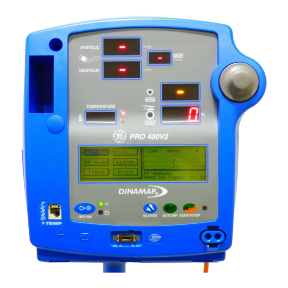
Page 21: Front Panel Controls And Indicators
Getting Started Front Panel Controls and Indicators 7 Systolic pressure display: 3-digit red LED indicates measured systolic BP in mmHg. 8 Active temperature probe holster: Temperature probe that is being used stored here (Models 200V2 and 400V2). 9 Diastolic pressure display: 3-digit red LED indicates measured diastolic BP in mmHg. - Page 22 14 External power indicator: Green LED indicates external power status and battery charging status of monitor. 15 Temperature probe connector: Temperature probe cable attaches here (Models 200V2 and 400V2). 16 ON/OFF switch: Controls on/off state of monitor; push for power on and push again for power off. 17 Battery power indicator: Yellow LED indicates operation and charge status of internal battery.
-
Page 23: Switching The Monitor On And Off
Getting Started Switching the Monitor On and Off To switch the DINAMAP PRO Monitor on, press and hold the power ON/OFF switch (16) for at least 10 seconds or press the rotor (21). As the Monitor powers up, it will run a short self-test routine, which will flash all the indicator lights and then beep the warning speaker. -
Page 24: Liquid Crystal Display (Lcd)
will be blanked except for a dash in the far-left systolic position, and any existing readings will be transferred to the LCD, which displays the message “Sleep Mode Active.” Moving the rotor or pressing a key will “wake up” the Monitor. -
Page 25: Using The Printer
Note: Make sure that the roll of paper is tightly wound. Any time the paper is loaded, the printer automatically prints a test strip with the DINAMAP ® PRO name on it. If no print is visible on the paper, check that the paper roll has been installed in the correct position (refer to diagram). -
Page 26: Storage
LCD will remain until new paper is installed and the printer door is closed. (See “Using the Menu System.”) Installing new paper will cause the DINAMAP PRO header to be printed, thereby confirming that the paper is installed correctly and that the printer is operational. The message next to “PRNT”... -
Page 27: Noninvasive Blood Pressure Determination
Using the Monitor Noninvasive Blood Pressure Determination Description The BP parameter is included in Models 100V2, 200V2, 300V2, and 400V2. Blood pressure is monitored noninvasively in the PRO Monitor by the oscillometric method, which measures the amplitude of the pressure oscillations within the blood pressure cuff. - Page 28 allowing SpO and predictive temperature determinations to be monitored and recorded (depending on Monitor model). In the Vitals (UK: All Obs) mode, the blood pressure is determined one time. Before each BP determination, the Monitor performs a test to ensure that the cuff pressure is below a specified level. The determination is delayed until this condition is met.
- Page 29 Using the Monitor examine the cuff site and the limb distal to the cuff regularly for signs of impeded blood flow. • Do not apply external pressure against cuff while monitoring. Doing so may cause inaccurate blood pressure values. • Use care when placing cuff on extremity used to monitor other patient parameters.
- Page 30 produce a peripheral pulse or the patient may have poor peripheral perfusion. Also, if a patient’s beat-to- beat pulse amplitude varies significantly (e.g., because of pulsus alternans, atrial fibrillation, or the use of a rapid-cycling artificial ventilator), blood pressure and pulse rate readings can be erratic, and an alternate measuring method should be used for confirmation.
-
Page 31: Procedures
Using the Monitor Procedures 1. Connect the end of the air hose which has quick-release clips to the cuff connector (30) on the front of the Monitor. Make sure that the hose is not kinked or compressed. Note: To disconnect the hose from the Monitor, squeeze the quick-release clips together and pull the plug from the cuff connector (30). - Page 32 5. Inspect cuff for damage. Replace cuff when aging, tearing, or weak closure is apparent. Do not inflate cuff when unwrapped. Precaution: Do not use cuff if structural integrity is suspect. 6. Connect the cuff to the air hose. Thread the cuff connectors onto the hose connectors until finger tight.
-
Page 33: Manual Mode
Using the Monitor Manual Mode To start a determination, press the START/STOP BP key (29). A normal, uninterrupted Manual cycle takes about 40 seconds. The cuff pressure must drop below 5 mmHg (neonate) or 15 mmHg (adult) before another determination can be started. -
Page 34: Stat Mode
When Auto mode is selected, a number at the right of the Auto button indicates the time interval between each reading. To change the time interval, choose the box around the number and turn the rotor until the desired interval is reached. -
Page 35: Turbo Temp
Using the Monitor initial target pressure selection for neonates is 110 mmHg. Artifact rejection is relaxed in the Stat mode for adult/ pediatric patients to allow for accelerated determinations. If a BP or Stat reading has been made previously, the first new systolic value will flash on the LED display (7) within a few seconds and will continue to flash until the end of the determination. -
Page 36: Predictive Mode
Temperature is shown on the temperature display in degrees Celsius or Fahrenheit, and the unit of measure is indicated by the °C °F display (13). The default, which is Celsius, can be changed in the Clinician Menu (please refer to the “Using the Menu System”... - Page 37 Using the Monitor When a monitor mode measurement is in progress, it is terminated when the probe is inserted into the probe holster. Note: These temperature readings are not stored in trends and not reported via host comms. General Warning •...
-
Page 38: Procedures For Oral Predictive Mode Determinations
used. To avoid cross contamination, use each cover only once. • If a patient’s temperature is below 96.0 °F, the unit will automatically switch from the normal mode into the monitor mode within 40 seconds. It will continue to monitor the patient’s temperature until the probe is removed from the patient and returned to the storage well. -
Page 39: Procedures For Rectal Predictive Mode Determinations
Using the Monitor 5. The determination begins automatically. Hold the temperature probe steady until the determination is complete. This takes approximately 10 seconds, during which time a “chase sequence” of arrows in the right-side of the Temperature window appears to indicate progress. 6. -
Page 40: Procedures For Monitor Mode Determinations (Axillary Determinations)
5. When the determination is complete, an audible tone sounds and the temperature appears on the display. 6. Remove the probe. Discard the disposable cover by holding the probe as you would a syringe and pressing the button on the probe handle. Place the probe in the probe holster. -
Page 41: Masimo Set* Spo2
Using the Monitor not display a final temperature. If this occurs, insert the probe into the probe holster, remove it again, and start a new measurement. • If an alarm is actively sounding, an audible tone will not sound. • If the probe is not inserted/placed within 30 seconds of probe removal, the Monitor may issue an alarm. - Page 42 automatically. Functional oxygen saturation (SpO ) of arterial blood is noninvasively and continuously monitored in the PRO Monitor using pulse oximetry technology from MASIMO SET ® . Functional SpO is the ratio of oxygenated hemoglobin to hemoglobin that is capable of transporting oxygen.
- Page 43 Using the Monitor counting down. Selecting Cancel will cancel the SpO alarm suspension and return to monitoring SpO If the Monitor is unable to detect a pulse for 10 seconds during normal SpO monitoring, the values in the LED flash, alternating patient values with dashes.
- Page 44 - the sensor is too tight - there is excessive illumination from light sources such as surgical lamp, a bilirubin lamp, or sunlight - a blood pressure cuff is inflated on the same extremity as the one with a SP0 sensor attached.
- Page 45 Using the Monitor image, and potential reduced accuracy of SpO measurements. Always remove oximetry devices and attachments from the MRI environment before scanning a patient. • The use of cardio-green and other intravascular dyes at certain concentrations may affect the accuracy of the measurement.
-
Page 46: Procedures
• Software development, software validation, and Risk and Hazard Analysis has been performed to a registered quality system. • Use or patient-applied parts are latex-free. Procedures 1. Select a sensor that is appropriate for the patient and the clinical situation. Warning: Do not use a damaged sensor or one with exposed electrical contacts. -
Page 47: Troubleshooting Masimo Set® Spo2 Parameter
Using the Monitor • Do not place a clip-on finger sensor on a patient’s thumb or across a child’s foot or hand. • Observe the sensor site to assure adequate distal circulation. Sensor sites should be checked as instructed in the Masimo Directions for Use. Different sites call for varying times between checks. - Page 48 replace it if necessary; move the sensor to a new site; or use a disposable adhesive sensor that may tolerate more motion. • Replace the sensor. PROBLEM: The SpO value or the pulse rate changes rapidly; the pulse amplitude bar is erratic. CAUSE: •...
- Page 49 Using the Monitor that has a blood pressure cuff, arterial catheter, or intravascular line. SOLUTION: • Check that calculations have been corrected appropriately for the relevant variable. In general, calculated saturation values are not as reliable as direct laboratory hemoximeter measurements. •...
-
Page 50: Nellcor® Oximax™ Spo2
• Consider increasing perfusion using heat. • If there is excessive light, cover the sensor with opaque material. PROBLEM: A sensor error indicating a bad sensor has occurred. CAUSE: • The sensor or cable may be defective, or the cabling may be improperly connected. - Page 51 Using the Monitor that are derived from the SpO signal. A tone sounds at a rate corresponding to the SpO saturation level. The pitch is highest at 100% oxygen saturation and becomes a little lower with each 1% decrease in saturation level. The Monitor can display a pulse amplitude bar and a plethysmographic waveform on the LCD (25).
- Page 52 normal SpO reporting of values when several consecutive good pulse determinations are made. General Warnings • Do not use the SpO function during magnetic resonance imaging (MRI). Adverse reactions include potential burns to patients as a result of contact with attachments heated by the MRI radio frequency pulse, potential degradation of the magnetic resonance image, and potential reduced accuracy of SpO...
-
Page 53: Procedures
Using the Monitor • Bright light sources (e.g., infrared heat lamps, bilirubin lights, direct sunlight, operating room lights) may interfere with the performance of the SpO function. To prevent such interference, cover the sensor with opaque material. General Notes • A patient’s vital signs may vary dramatically during the use of cardiovascular agents such as those that raise or lower blood pressure or those that increase or decrease heart rate. -
Page 54: Patient Safety
• Excessive pressure from the sensor may cause necrosis of the skin. • For additional warnings and information, refer to the ® NELLCOR sensor’s directions for use. Monitor performance: •When an SpO sensor is on a limb that has a blood pressure cuff, the SpO data will not be valid when the cuff is inflated. -
Page 55: Troubleshooting The Nellcor Spo2 Parameter
Using the Monitor • Place the sensor so that the LEDs and the photodiode are opposite each other. 3. Plug the SpO sensor into the SpO sensor extension cable. Then plug the SpO sensor extension cable into the sensor connector (18). 4. - Page 56 • An electrosurgical unit (ESU) may be interfering with performance. SOLUTION: Check the patient. • If possible, keep the patient still; check whether the sensor is applied securely and properly, and replace it if necessary; move the sensor to a new site; use a sensor that tolerates more motion.
- Page 57 Using the Monitor calculated saturation values are not as reliable as direct laboratory hemoximeter measurements. • If there is excessive light, cover the sensor with opaque material. • Circulation distal to the sensor site should be checked routinely. The site must be inspected every 8 hours to ensure adhesion, skin integrity, and correct optical alignment.
- Page 58 CAUSE: • The sensor or cable may be defective, or the cabling may be improperly connected. SOLUTION: Check the patient. • If possible, keep the patient still; check whether the sensor/cable is applied securely and properly, and replace it if necessary. •...
-
Page 59: Using The Menu System
Using the Menu System Introduction The PRO Monitor is equipped with a liquid crystal display (25) and a rotor (21). Used together, these allow the operator to view and edit most of the Monitor’s parameters and functions. When the Monitor is in use, a number of option buttons appear on the liquid crystal display (LCD). -
Page 60: Normal Mode Menu
Normal Mode Menu... -
Page 61: Clinician Mode Menu
Using the Menu System C l i n i c i a n M o d e M e n u... -
Page 62: Rotor
Rotor Rotating the rotor causes option buttons to be highlighted (light text on a dark background). Turning the rotor produces a click. Turning it clockwise moves the highlighting clockwise over the available buttons, while turning it counterclockwise reverses the direction of the highlighting. Pressing the rotor selects the highlighted button and produces an audible tone. -
Page 63: Vitals Button (Uk: All Obs)
Using the Menu System Vitals Button (UK: All Obs) Selection of this button initiates a BP determination while allowing SpO and predictive temperature determinations to be monitored and recorded (depending on Monitor model). When the Vitals determination is complete, a single “warble” sounds and all patient data are displayed on the LEDs and held for 2 minutes. -
Page 64: Print
Note: If the SpO plethysmograph is displayed on the LCD, the waveform pauses for 2 minutes or until the Clear button is selected. SpO values are also retained the same manner as the BP and Temperature values. Print Selection of this button causes the current data to be printed. Notes •... -
Page 65: Manual
Using the Menu System operating mode returns to the default setting of Manual. The default setting of Manual can be overridden to return to the previous user-selected setting (Auto or Manual) by selecting Set BP under the Service menu. To cancel an Auto BP determination, select the START/STOP key. -
Page 66: Main
Main Selection of this button returns the user to the Main menu. Alarms Button Selection of this button displays the Alarms menu. This menu is used to adjust the violation limits for BP, Pulse Rate, and . The values and ranges for these parameters are not stored when the Monitor is turned off. -
Page 67: Auto
Using the Menu System Auto Selection of this button updates the alarm limits relative to the current parameter values. Pressing this button cancels any limit violation alarm that is invalided by this automatic limit change. The alarm limits are updated as follows: Notes •... -
Page 68: Display
Display Selection of this button allows the operator to view the trend data. Note: If the trend data have been lost (e.g., if the clock settings have been changed), the message “Trend Empty” will appear instead of the Newer, Older, and Print page buttons. -
Page 69: Main
Using the Menu System Main Selection of this button returns the user to the Main menu. Print Button Selection of this button displays the Print menu. Auto/Man Pressing this button toggles between Automatic and Manual Printing modes. The current mode is displayed on Area 3 of the LCD. -
Page 70: More
More... Menu This menu is used to set the various operating modes of the Monitor. Button (Models 300V2 and 400V2) Selection of this button displays the SpO mode menu, which is used to set the SpO pulse tone volume and SpO Average (Masimo ONLY). -
Page 71: Main
Using the Menu System Response Mode (Nellcor Only) Response mode allows the user to specify the averaging technique to optimize measurements in the presence of various patient movement. Choose Mode 1 (normal Response) when patients are active as in exercise protocols. Choose Mode 2 (Fast response;... -
Page 72: Pwr Sav (Sleep Mode)
Pwr Sav (Sleep Mode) Selection of this button allows the operator to specify the time, in minutes, that elapses before the Monitor goes into “sleep” mode (LEDs blanked and LCD displaying values from LEDs). Sleep mode is available only if the Monitor is operating from its battery. -
Page 73: Time
Using the Menu System • A BP determination is started through the host comm • The displayed NIBP or Temperature values are too old and need to be refreshed Time Selection of this button allows the operator to change the internal time and date of the Monitor. -
Page 74: Main
Main Selection of this button returns the user to the Main menu. Temp Selection of this button displays the temperature submenu, which allows the user to choose the temperature label. When C (Celsius) is selected, the °C indicator lights. When F (Fahrenheit) is selected, the °F indicator lights. -
Page 75: Display Button
Using the Menu System Display Button Selection of this button displays the Display mode menu. This menu is used to specify whether Area 2 of the LCD will display SpO or BP data. If neither SpO nor 3 NIBP is selected, Area 2 of the LCD will remain blank except for the pulse amplitude bar (if SpO data are available) and any... -
Page 76: Clinician Menu
Clinician Menu Press. Selection of this button displays a panel for setting the default BP target inflation pressure. Adjusting the default target pressure will automatically update the current inflation target pressure and will be used for the next reading. The range of adjustment is 100 mmHg to 180 mmHg, and the setting is retained when the Monitor is turned off. - Page 77 Using the Menu System O K . S e l e c t i o n o f t h i s b u t t o n r e t u r n s t h e u s e r t o t h e C l i n i c i a n m e n u .
- Page 78 after power-off and returns the Monitor to the More... menu. Selection of No restores the Print mode to the Manual mode after power-off and returns the Monitor to the More... menu. Selection of Cancel returns the Monitor to the More... menu. .
-
Page 79: Error And Warning Messages
Using the Menu System Main. Selection of this button returns the user to the Main menu. Silence. Selection of this button will cause all alarms except the FAILSAFE alarm to be muted. A confirmation menu will appear in Area 2 of the LED. Selection of either Yes or No returns the user to the Clinician mode menu. -
Page 80: Alarms Button
Alarm conditions are addressed in two ways: the Alarms button and OK button. Alarms Button Selection of this button takes the user to the Alarms menu, where the alarm limits can be adjusted. This button is available only when a parameter alarm limit has been violated. -
Page 81: Appendix A
Appendix A Technical Specifications Cuff Pressure Range 0 to 290 mmHg (adult/ped) (Normal operating range) 0 to 145 mmHg (neonate) Default Target: Cuff Inflation 150 ± 15 mmHg (adult/ped) 110 ± 15 mmHg (neonate) Target Cuff Inflation: 100 to 250 mmHg (adult/ped) Adjustment Range 100 to 140 mmHg (neonate) (in 5 mmHg increments) -
Page 82: Turbo´temp Temperature
TURBO«TEMP Temperature Scale °Fahrenheit (F) °Celsius (C) Range Predictive mode Max: 41.1° C; 106.0° F Min: 35.6° C; 96.0° F Monitor mode Max: 43.3° C; 110.0° F Min: 26.7° C; 80.0° F Monitor mode accuracy ± 0.1° C ± 0.2° F (when tested in a calibrated liquid bath;... -
Page 83: Pulse Rate
Appendix A Pulse Rate Without Motion 20 to 250 beats/min ±3 digits With Motion normal physiologic range 55 to 125 beats/min ±5 digits Low Perfusion 20 to 250 beats/min ±3 digits *Adult specifications are shown for OXIMAX MAX-A and MAX-N sensors. Neonate specifications are shown for OXIMAX MAX-N. -
Page 84: Measurement Range
Nellcor Patents 4,621,643; 4,653,498; 4,700,708; 4,770,179; 4,802,486; 4,869,254; 4,928,692; 4,934,372; 5,078,136; 5,351,685; 5,421,329; 5,485,847; 5,533,507; 5,577,500; 5,803,910; 5,853,364; 5,865,736; 6,083,172; Re. 35,122 and, international equivalents. Masimo SET SpO Measurement Range 1 to 100% Pulse Rate 25 to 240 beats/min Perfusion Range 0.02 to 20% Accuracy and Motion Tolerance Saturation... -
Page 85: Masimo® Sensor Accuracy
Appendix A standard deviation. Plus or minus one standard deviation encompasses 68% of the population. ® ‡The Masimo SET parameter has been validated for low perfusion accuracy in bench top testing against a Biotek Index 2 simulator and Masimo’s simulator with signal strengths of greater than 0.02% and a % transmission of greater than 5% for saturations ranging from 70 to 100%. -
Page 86: Default Settings
Default Settings HIGH: 100 LOW: 90 Sensitivity Mode 2 (for low perfusion-Default) Averaging Time 12 seconds FastSAT Mode 0 (for Off) Masimo Patents 5,482,036; 5,490,505; 5,632,272; 5,685,299; 5,758,644; 5,769,785; 6,002,952; 6,036,642; 6,067,462; 6,206,830; 6,157,850, and international equivalents. Mechanical Dimensions Height: 9.8 in (25.0 cm) Width: 9.8 in (24.8 cm) Depth: 6.9 in (17.5 cm) Weight, Including Battery... -
Page 87: Environmental
Appendix A AC input is protected by two internal fuses, replaceable by qualified service personnel only. DC input line is protected by an internal auto- resetting fuse. Battery: 12 volt, 2.3 amp- hours protected by internal auto-resetting fuse. Minimum operation time: 2 hrs (5 min cycle with adult cuff at 25 °C with power save mode enabled) from full... - Page 88 (Group 1, Class A) for radiated and conducted emissions. IPX1 ® The DINAMAP PRO Monitor is protected against vertically falling drops of water and conforms to IEC-529 standard at level of IPX1. Vertically falling drops of water shall have no harmful.
-
Page 89: Appendix B
Appendix B Alarm Codes All alarm indications are accompanied by an audible signal unless Alarm Silence is selected. A microprocessor system failure will generate a high-pitched audible alarm regardless of the setting of the Alarm Silence switch. There are three categories of alarms: patient alarms, system alarms, and fail-safe alarm. -
Page 90: Hierarchy Of Alarms
Hierarchy of Alarms ® Alarms in the DINAMAP PRO Monitor are in three priority levels. They are: Alarm Priority Level Fail-safe Patient and system 2 (High priority alarm) Low battery The Priority 1 alarm (i.e., Fail-safe) will override any other alarm. - Page 91 Appendix B...
- Page 93 Appendix B...
-
Page 95: Principles Of Noninvasive Blood Pressure Determination
Appendix C Principles of Noninvasive Blood Pressure Determination The oscillometric method of determining NIBP is accomplished by a sensitive transducer which measures cuff pressure and minute pressure oscillations within the cuff. A single determination (in normal mode) is initiated before taking repeated determinations in auto or stat mode. - Page 96 Full NIBP Determination Sequence for Adult At each step the microprocessor stores cuff pressure, the matched pulse amplitude, and the time between successive pulses. The stepped deflation and matched pulse detection continues until diastolic pressure is determined or total cuff pressure falls below 8 mmHg.
-
Page 97: Systolic Search
Appendix C NIBP - Auto Mode Systolic Search If systolic pressure is not found, the NIBP parameter can search at cuff pressures higher than the initial target pressure. The parameter will inflate the cuff above the initial target pressure to get more data in the systolic region. The maximum pressure allowed in systolic search is limited by the normal range for cuff pressures. -
Page 98: Reverting And Accelerated Determination
Reverting and Accelerated Determination When the determination data does not agree with the previous determination, there may be a reversion to a determination with more steps. The algorithm will try to make an accelerated determination of blood pressure if it has been 16 minutes or less since the last determination. -
Page 99: Appendix D
Appendix D Reorder Codes PROD PRODUCT CODE DINAMAP PRO Monitor Operations Manual-English 2018548-001 DINAMAP PRO Monitor Service Manual 2018553-001 Battery, 12V Lead Acid 2010422-001 Printer Paper (box of 10) 089100 DINAMAP Rolling Stand 003215 Isolated Remote Alarm Cable Assembly 487208CR ILC Cable Assembly ILC1926 &... - Page 100 SPO2: ® NELLCOR Pulse Oximeter Cable DOC-10 2008773-001 DuraSensor Adult Oxygen Sensor DS100A ® Masimo Adult Reusable Sensor, 1/Bx (NR125) 2009745-001 Cable (PC08) 2009743-001...
-
Page 101: Appendix E
Appendix E Warranty, Service, and Spare Parts Warning: There are no user serviceable parts inside the ® DINAMAP PRO Monitor. Refer all servicing to qualified personnel. Warranty All repairs on products under warranty must be performed or approved by GE Medical Systems Information Technologies. -
Page 102: Repairs
Repairs If your product requires warranty, extended warranty, or non-warranty repair service, call GE Medical Systems Information Technologies and a representative will assist you. Estimates for non-warranty repairs are provided at no charge; however, the product must be sent to GE Medical Systems Information Technologies for an estimate. -
Page 103: Appendix F
Appendix F Maintenance Cleaning the Monitor The Monitor and accessories are to be kept clean and used according to the instructions provided here and in the Service Manual. The exterior of the Monitor may be wiped clean with a soft cloth slightly dampened with mild detergents. -
Page 104: Procedure
• Spray bottles Procedure 1. Prepare the enzymatic detergent according to the manufacturer’s instructions and the 10% bleach solution, in separate spray bottles. 2. Spray the detergent liberally on device. If the material is dried on, allow the cuff to sit for 1 minute. For soil on the soft part of the closure or the cuff itself, wipe the material off with a soft cloth. -
Page 105: Storage And Battery Care
Appendix F are damaged, they must be disposed of as advised in Appendix F. Storage and Battery Care If it becomes necessary to store the Monitor for an extended period of time, first fully charge then remove the battery. Then store the Monitor and the battery in the original packaging materials. -
Page 106: Fuses
Caution: Refer calibration and leak testing to qualified service personnel. Full calibration details are available in the DINAMAP PRO Monitor Service Manual, available from GE Medical Systems Information Technologies. -
Page 107: Disposal Of Product Waste
Appendix F Disposal of Product Waste As you use the PRO Monitor, you will accumulate solid wastes that require proper disposal or recycling. These include batteries, patient applied parts, and packaging material. Batteries Caution: Do not incinerate batteries. The sealed, rechargeable backup battery contains lead and can be recycled. -
Page 109: Appendix G
Appendix G Host Port Connector (rear panel) WARNING! Auxiliary equipment connected to the ® DINAMAP PRO Monitor will result in the formation of an electromedical system and thus, must comply with the requirements of EN 60601-1-1/ IEC 601-1. All host port... - Page 112 0086 2018548-001 A gemedical.com European Representative World Headquarters Asia Headquarters GE Medical Systems GE Medical Systems GE Medical Systems Information Technologies GmbH Information Technologies, Inc. Information Technologies Asia Postfach 60 02 65 8200 West Tower Avenue 24th Floor, Shanghai MAXDO D-79032 Freiburg Milwaukee, WI 53223 USA Center,...
Need help?
Do you have a question about the Pro 100V2 and is the answer not in the manual?
Questions and answers