
Subscribe to Our Youtube Channel
Related Manuals for ReDeal AP160N


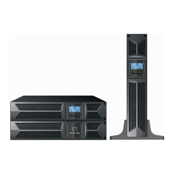
Summary of Contents for ReDeal AP160N
-
Page 1: User Manual
Deal USER MANUAL On-Line UPS Model AP160N 1000VA/2000VA/3000VA Uninterruptible Power Supply System www.redeal.pt... -
Page 2: Table Of Contents
6.4 NO output mode ................. 26 6.5 EPO (Emergency Power Off) ............. 26 6.6 ECO mode (Economy mode) ............. 26 6.7 Converter mode.................. 27 6.8 Abnormal mode .................. 27 7. Setting by LCD Module..............28 8. Trouble Shooting................30 9. Maintenance..................32 www.redeal.pt... - Page 3 11. Communication Port ................ 34 11.1 RS-232 and USB communication ports ........... 34 11.2 RS-232 port ..................35 11.3 USB port ................... 35 11.4 Installing a Serial Network Management Card (optional) ....35 12. Software .................... 37 Appendix: Rear panel ................38 www.redeal.pt...
-
Page 4: Safety And Emc Instructions
★ The equipment is powered by more than one source. 1.1.1 Inspection of Unit Inspect the UPS upon receiving. If the UPS is apparently damaged during the shipment, please keep the box and packing material in original form for the carrier and notify the carrier and dealer immediately. www.redeal.pt... - Page 5 Slide down the UPS vertically and put two UPS stands at the end of the tower. Place down the UPS into two stands carefully. Pull out the LCD box and rotate it in a clockwise direction to 90 degree and then push it back in the front panel. www.redeal.pt...
-
Page 6: Ebm Installation (Optional)
3. Connect the Earth line from UPS (port A ) to EBM (port B) 4. Take off the front panel, and connect the battery terminal (A) from UPS to EBM terminal (B) shown as below. Users need to remove the small gate(C) www.redeal.pt... - Page 7 EBM to pass through the gate and then reassemble front panel. www.redeal.pt...
- Page 8 Unscrew Unscrew Connecting the Multiple EBMs 1KVA / 2KVA and 3KVA UPS include external battery port that allows users to connect multiple EBM in order to provide additional backup time. Follow the procedure to install multiple EBM as below. www.redeal.pt...
- Page 9 (D) from the first EBM to the battery terminal (E) from the second EBM. Users need to remove the small gate(C) on side of the front panel to allow the outlet wire of the EBM to pass through the gate and then reassemble front panel. www.redeal.pt...
-
Page 10: Operation
★ Do not remove the enclosure. This system is to be serviced by qualified service personnel only. ★ Remove the protective panel only after disconnecting the terminal connections. ★ Use No. 12 AWG (for 3K-KS input wire), 90°C copper wire and 4.4 lb-in www.redeal.pt... -
Page 11: Maintenance, Servicing And Faults
★ Do not dismantle the UPS, except the qualified maintenance personnel. 1.3.1 UPS and Battery Care For the best preventive maintenance, keep the area around the UPS clean and dust-free. If the atmosphere is very dusty, clean the outside of the system www.redeal.pt... - Page 12 Do not dispose of battery in a fire. Batteries may explode when exposed to flame. Proper disposal of batteries is required. Refer to your local codes for disposal requirements. Do not open or mutilate the battery. Released toxic electrolyte is harmful to skin and eyes. www.redeal.pt...
- Page 13 Remove the right inner battery bracket. Pull the battery pack out onto flat area. Install new battery pack into UPS. Screw up the battery bracket and reconnect the battery cable A and B Re-install the front panel back to UPS. www.redeal.pt...
-
Page 14: Transport
UPS, battery pack, and batteries. 1.4 Transport ★ Please transport the UPS only in the original packaging (to protect against shock and impact). 1.5 Storage ★ The UPS must be stockpiled in the room where it is ventilated and dry. www.redeal.pt... -
Page 15: Standards
Voltage Fluctuation and Flicker..:IEC/EN 61000-3-3 *EMS ESD...........:IEC/EN 61000-4-2 Level 3 RS.............:IEC/EN 61000-4-3 Level 3 EFT............:IEC/EN 61000-4-4 Level 4 SURGE..........:IEC/EN 61000-4-5 Level 4 CS……………………………………...:IEC/EN 61000-4-6 Level 3 MS……………………………………..: IEC/EN 61000-4-8 Level 3 Voltage Dips………………………….: IEC/EN 61000-4-11 Low Frequency Signals.....:IEC/EN 61000-2-2 www.redeal.pt... -
Page 16: Description Of Commonly Used Symbols
2. Description of Commonly Used Symbols Some or all of the following symbols may be used in this manual. It is advisable to familiarize yourself with them and understand their meaning: www.redeal.pt... -
Page 17: Introduction
Model No. on the rear panel of the UPS. Model No. Type Model No. Type 1K-KS Extended backup Standard 2K-KS time 3K-KS “KS” Model: Extended backup time www.redeal.pt... -
Page 18: Panel Description
The output voltage, frequency, Bypass disable/enable and operating Button mode in No output or Bypass mode, Two Load segments in output mode, Battery string in all mode, could be selected by pressing Enter Select-Button, and confirmed by pressing Enter-Button. Button www.redeal.pt... -
Page 19: The Lcd Display
It Indicates the operating mode It indicates the UPS is in setting or Fault kind or Warning kind, mode. several warning kinds at the It indicates the UPS is in Fault same time could be displayed alternately. mode or has some warnings. www.redeal.pt... -
Page 20: Connection And Operation
NFB(Non-Fuse Breaker) instead of the traditional combination kit including breaker and fuse. When selecting the NFB, the user can refer to below table. UPS INPUT NFB & Power Cord & Socket Model No. VOLTAGE CURRENT 1K & 1K-KS 300Vac 2K & 1K-KS 300Vac 3K & 1K-KS 300Vac www.redeal.pt... - Page 21 Normally the EPO connector is closed with a wire on the rear panel. Once the connector is open, the UPS would stop the output until the EPO status is disabled. Enable the EPO status Disable the EPO status ( UPS output is OFF ) ( normal status ) www.redeal.pt...
-
Page 22: Battery Charge
1 second, the UPS would detect whether the battery is connected or the battery is low immediately. Also the UPS could do the test automatically and periodically, the period time could be set by user, the default value is 7 days. www.redeal.pt... -
Page 23: Turn Off The Ups
(5) Remove front panel, connect the battery via Anderson PP45 connectors. Prepare the battery cable which should be able to carry the current of >50A for all models, the cross section area should be great than 4 mm www.redeal.pt... - Page 24 A DC breaker must be connected between the UPS and external battery. Caution: The output sockets of the UPS system may still be electrically live even if the power supply system has been disconnected or the Bypass switch is on “OFF” position. www.redeal.pt...
-
Page 25: Operating Mode For All Models
■ ■ ■ ■ The Line mode If output overloaded, alarm will keep twice every second. You should get rid of some unnecessary loads one by one to decrease the loads connected to the UPS less than 90% of its nominal power capacity. www.redeal.pt... -
Page 26: Battery Mode
UPS output and the load level could be displayed. The UPS will beep once every 2 minutes in bypass mode. The “bYPA” string indicate the UPS is working in the bypass mode. ■ ■ ■ ■ The Bypass mode www.redeal.pt... -
Page 27: No Output Mode
1) It could be enabled through the LCD setting or the software (Winpower, etc.). 2) It is attention that the transfer time of UPS output from ECO mode to battery mode is less than 10ms. But it is still too long for some sensitive load. www.redeal.pt... -
Page 28: Converter Mode
UPS, and the background light become red. For example “SHOR” would be shown when the load or the UPS output is short. The LCD display is shown in the following diagram. www.redeal.pt... -
Page 29: Setting By Lcd Module
“208V”, “220V”, “230V”, “240V” at any time; The only one frequency value could be selected in “50Hz”, “60Hz” at any time; Bypass status could be selected in “000” or “001”(Here 000 means Bypass Disable,001 means Bypass Enable),The UPS would turn to bypass mode in www.redeal.pt... - Page 30 “Enter” button to set mode, then “UPS” flickering; Step 5: “ECO” flickering after pressing the “Select” button; Step 6: “CVF” flickering after pressing the “Select” button again. Press the “Enter” button to make sure to change the mode. Short touch “Enter” button to exit setting mode. www.redeal.pt...
-
Page 31: Trouble Shooting
Battery is over charged Stop charging to battery automatically, and after the battery voltage is normal and the mains is normal, charge automatically again. Battery low Battery voltage is low When audible alarm sounding every second, battery is almost empty. www.redeal.pt... - Page 32 3. LCD display status, Buzzer alarm status 4. Utility power condition, load type and capacity, environment temperature, ventilation condition 5. The information (battery capacity, quantity) of external battery pack if the UPS is “S” model 6. Other information for complete description of the problem www.redeal.pt...
-
Page 33: Maintenance
Reconnect the new batteries to the UPS by following section 5.8. Then turn on the battery breaker and press the ON switch to make the UPS do the battery test, check whether the battery information is normal. www.redeal.pt... -
Page 34: Technical Data
Ambient Temperature 0 oC to 40 oC Operating humidity < 95% Altitude < 1000m Storage temperature 0 oC to 45 oC 10.3 Typical backup time (Typical values at 25°C in minutes:) Model No. 100 % Load 50 % Load www.redeal.pt... -
Page 35: Dimensions And Weights
UPS. The software polls the UPS for detailed information on the status of the power environment. If a power emergency occurs, the software initiates the saving of all data and an orderly shutdown of the equipment www.redeal.pt... -
Page 36: Rs-232 Port
11.4 Installing a Serial Network Management Card (optional) Each UPS has one available communication bay, which supports the optional Serial Network Management Card. After you install a Serial Network Management Card, you can connect an environmental monitoring probe to the UPS. www.redeal.pt... - Page 37 3. Insert the Serial Network Management Card into the slot on the UPS. 4. Secure the Serial Network Management Card to the UPS with both screws. For more information about the Serial Network Management Card, see the Serial Network Management Card User's Guide. www.redeal.pt...
-
Page 38: Software
When downloading all required files from the internet, enter the serial No: 511C1-01220-0100-478DF2A to install the software. When your computer restarts, the WinPower software will appear as a green plug icon located in the system tray, near the clock. www.redeal.pt... -
Page 39: Appendix: Rear Panel
The UPS rear panel description table and pictures are shown as below: Function(1KVA – 2KVA – 3KVA) AC Output EPO / Dry input Communication Port USB Port AC Input Dry out SNMP slot RS232 Modem/Network Surge Protection Earth Line connection 1K, 2K Standard & 1K-KS rear panel 2K-KS rear panel www.redeal.pt... - Page 40 3K Standard model rear panel 3K-KS model rear panel The EBM rear panel description table and picture are shown as below: Function(36V & 48V & 72V EBM) Earth Line Port 36V &48V&72V EBM rear panel 614-03804-00 www.redeal.pt...
Need help?
Do you have a question about the AP160N and is the answer not in the manual?
Questions and answers