Table of Contents
Advertisement
Quick Links
- 1 Name of Parts
- 2 Compressor Room View and Parts List
- 3 How to Replace the Main Parts
- 4 Replacing the Lower Zone Led Light Assembly ,Evaporator, Ptc Heater, Fan Motors & Sensors
- 5 Replace the Condenser Fan Motor ,Compressor Starter & Protector
- 6 Replacing Condenser Fan Motor/Compressor Starter/Overload Protector
- 7 Troubleshooting
- 8 Troubles Shooting Guide
- Download this manual
See also:
Owner's Manual
Advertisement
Table of Contents

Subscribe to Our Youtube Channel
Related Manuals for EdgeStar CWR460DZ


Summary of Contents for EdgeStar CWR460DZ
- Page 1 WINE CELLAR SERVICE MANUAL CAUTION BEFORE SERVICING THE UNIT, READ THE "SAFETY PRECAUTIONS" IN THIS MANUAL. DUAL ZONE MODEL:CWR460DZ...
-
Page 2: Table Of Contents
CONTENTS SAFETY PRECAUTIONS ..…………………………………………………………………………….…………………………………….…2 NAME OF PARTS…………………………………………………………………………………………………..……..…….………………3 REFRIGERANT CYCLE DIAGRAM…………………………………………………………………………………………...………..…….3 COMPRESSOR ROOM VIEW AND PARTS LIST…………………………………………………..…….……………….………..……..4 HOW TO REVERSE THE DOOR SWING……………………………………………………………………….……………………..…...4-5 HOW TO ATTACHING THE DOOR HANDLE…………………………………………………………….………………………………….5 HOW TO REMOVE THE SHELVES………………….…………………………………………………………..……..……………….…….6 HOW TO REPLACE THE MAIN PARTS………………………………………………………………………………..…………………6-11 REPLACING THE CONTROL PCB , DISPLAY PCB ,UPPER ZONE SENSER & UPPER ZONE LED ASSEMBLY …..…….…6-7 REPLACE THE POWER PCB &... -
Page 3: Name Of Parts
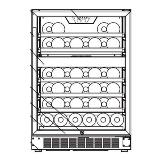
1. NAME OF PARTS 1. DIGITAL CONTROL PANEL 2. GLASS DOOR 3. STAINLESS STEEL HANDLE 4. MIDDLE PARTITION 5. LARGE SHELVES 6. SECURITY LOCK 7. BOTTOM SHELF 8. BOTTOM GRILLE 9. LEVELING LEGS 10. CABINET REFRIGERANT CYCLE DIAGRAM 1. Compressor 2. -
Page 4: Compressor Room View And Parts List
3. COMPRESSOR ROOM VIEW AND PARTS LIST 1. Junction Box 2. Electrical Box of Compressor 3. Process Pipe 4. Outlet Pipe of Condenser 5. Compressor 6. Dry Filter 7. Dry Filter Clamp 8. Suction Pipe 9. Capillary 10. Discharge Pipe 11. -
Page 5: How To Attaching The Door Handle
5. Remove the lower door hinge from the right side. 7. Install the lower hinge supporter together with the Remove the three screws that are used to fix the bush to the designated position. bottom grille with cabinet then install the three screws at the designated position at the right side. -
Page 6: How To Remove The Shelves
6. HOW TO REMOVE THE SHELVES To prevent damaging the door gasket, make sure to have the door all the way opened when pulling the bottom shelf out of the rail compartment. For easy access to the storage content, you must pull the shelf approximately 1/2 out of the rail compartment, however this unit was designed with a plastic post on each sides of the shelf track to prevent bottles from falling. - Page 7 9. Press the plastic nail supporting the control PCB 6. Remove four screws that are used to fix control with forefinger and thumb, pull the control PCB PCB box with the cabinet. upward,take away it ,then you can replace the new control PCB.
-
Page 8: Replace The Power Pcb & Transforme
7.2 REPLACING THE POWER PCB AND TRANSFORMER 1. Remove the three screws that are used to fix the 2. Disconnect all connectors on the Power PCB in the junction box with the cabinet in the compressor room. junction box then you can replace the Power PCB and Transformer. - Page 9 7. Disconnect the wires then you can replace t h e 11. Disconnect the housing from the LED light evaporator fan motor and lower zone fan motor. assembly.In this step, If it’s necessary, you can replace the LED light assembly. 12.
- Page 10 B. Take away the sensor cover from the rear air duct 15. The defrost senser is located in the following position. cover. 16. The PTC heater is located in the following position. C. Take away the sensor from sensor cover. D.
-
Page 11: Replace The Condenser Fan Motor ,Compressor Starter & Protector
7.4 REPLACING THE CONDENSER FAN MOTOR ,COMPRESSOR PTC STARTER AND OVERLOAD PROTECTOR 1. Remove the two screws that are used to fix the 4. Remove the clamp that is used to fix the junction condenser fan motor with the compressor base. box of compressor . -
Page 12: Adjustment
8. ADJUSTMENT 8.1 COOLING SYSTEM FAULTS HOW TO DIAGNOSE FAULTS It should take approximately 3 hours to reach the lowest setting temperature of 5℃ for an empty unit (assuming ambient temp of 32 degrees centigrade and continuous operation). If not, check the compressor, cooling fans, controller, and sensors. -
Page 13: Noise Of Wine Cooler
verifying no bad connections replace the fan unit . 2. How to check the PTC heater Check the resistance of PTC heater using a Multimeter; the reading should be approx 1.5 KΩ (assuming normal temperature), if open circuits Replace the PTC heater having once verified the connections to the PTC heater.Replace new one. -
Page 14: Description Of Control Pcb & Power Pcb
REMEDY: 1>. Replace the door gasket or close the door well. If the door gasket is slightly not air-proof, it can be repaired by the heat dryer.Aiming at the distortion of the gasket with the heat dryer, and move up and down until it expand to the normal state. -
Page 15: Troubleshooting
10. TROUBLESHOOTING 10.1 Troubleshooting Guide PROBLEM POSSIBLE CAUSE Not plugged in. Wine Chiller does not operate. The appliance is turned off. The circuit breaker tripped or a blown fuse. Check temperature control setting. External environment may require a higher setting. Wine Chiller is not cold enough.
Need help?
Do you have a question about the CWR460DZ and is the answer not in the manual?
Questions and answers