Table of Contents
Advertisement
SPLIT-TYPE AIR CONDITIONERS
SERVICE MANUAL
Models
MU-GE50VB-
MUH-GE50VB-
NOTE:
• This service manual describes technical data of outdoor units.
E1
E1
CONTENTS
1. TECHNICAL CHANGES ··································· 2
2. PART NAMES AND FUNCTIONS ····················· 3
3. SPECIFICATION ················································ 3
4. NOISE CRITERIA CURVES ······························ 4
5. OUTLINES AND DIMENSIONS ························ 5
6. WIRING DIAGRAM ············································ 6
7. REFRIGERANT SYSTEM DIAGRAM ··············· 7
8. PERFORMANCE CURVES ······························· 8
9. ACTUATOR CONTROL ··································· 16
10. SERVICE FUNCTIONS ···································· 17
11. TROUBLESHOOTING ····································· 17
12. DISASSEMBLY INSTRUCTIONS ···················· 23
PARTS CATALOG (OBB530)
No. OBH530
HFC
utilized
R410A
Indoor unit service manual
MS/MSH-GE
VB Series (OBH529)
•
Advertisement
Table of Contents

Subscribe to Our Youtube Channel
Related Manuals for Mitsubishi Electric MU-GE50VB- E1


Summary of Contents for Mitsubishi Electric MU-GE50VB- E1
-
Page 1: Table Of Contents
SPLIT-TYPE AIR CONDITIONERS OUTDOOR UNIT No. OBH530 SERVICE MANUAL utilized R410A Models MU-GE50VB- MUH-GE50VB- Indoor unit service manual MS/MSH-GE VB Series (OBH529) • CONTENTS 1. TECHNICAL CHANGES ··································· 2 2. PART NAMES AND FUNCTIONS ····················· 3 3. SPECIFICATION ················································ 3 4. -
Page 2: Technical Changes
TECHNICAL CHANGES MU-GA50VB- MU-GE50VB- 1. Unit size has been changed. (W 850 mm × H 605 mm × D 290 mm W 800 mm × H 550 mm × D 285 mm) 2. Outdoor fan motor has been changed. (RA6V50-PA RA6V33-KA) MUH-GA50VB- MUH-GE50VB-... -
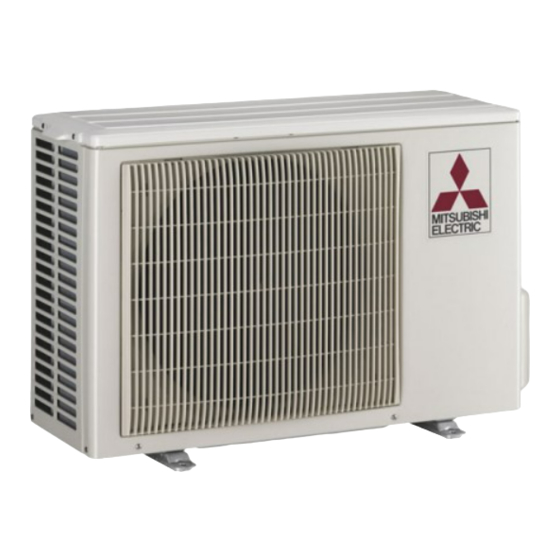
Page 3: Part Names And Functions
PART NAMES AND FUNCTIONS MU-GE50VB MUH-GE50VB MUH-GE50VB ACCESSORIES <Outdoor unit: MUH type> Air inlet Drain socket back and side Piping Drain hose Air outlet Drain outlet SPECIFICATION Outdoor model MU-GE50VB MUH-GE50VB Function Cooling Cooling Heating Single phase Single phase Power supply 230 V, 50 Hz 230 V, 50 Hz Capacity... -
Page 4: Noise Criteria Curves
NOISE CRITERIA CURVES MU-GE50VB MUH-GE50VB FUNCTION SPL(dB LINE FUNCTION SPL(dB LINE COOLING COOL HEATING Test conditions, Test conditions, Cooling :Dry-bulb temperature35°C Wet-bulb temperature24°C Cooling :Dry-bulb temperature35°C Wet-bulb temperature24°C Heating :Dry-bulb temperature 7°C Wet-bulb temperature 6°C NC-70 NC-70 NC-60 NC-60 NC-50 NC-50 NC-40 NC-40... -
Page 5: Outlines And Dimensions
OUTLINES AND DIMENSIONS MU-GE50VB MUH-GE50VB Unit: mm OUTDOOR UNIT REQUIRED SPACE Basically open 100mm or more without any obstruction in front and on both sides of the unit. Drain hole ø42 Air in Air in Open two sides of left, right, or rear side. -
Page 6: Wiring Diagram
WIRING DIAGRAM MU-GE50VB MUH-GE50VB... -
Page 7: Refrigerant System Diagram
REFRIGERANT SYSTEM DIAGRAM MU-GE50VB Unit :mm OUTDOOR UNIT Refrigerant pipe 12.7 (with heat insulator) Muffler Stop valve Outdoor (with service port) heat Flared connection exchanger Compressor Flared connection Strainer Stop valve #100 Capillary tube 3.0 x 1.6 x 450 Refrigerant pipe 6.35 (with heat insulator) MUH-GE50VB OUTDOOR UNIT... -
Page 8: Performance Curves
MAX. REFRIGERANT PIPING LENGTH Refrigerant piping: m Piping size O.D: mm Length of connecting pipe: m Max. length Max. height Model Outdoor unit Liquid Indoor unit Gas 0 MU-GE50VB Gas 0.43 12.7 6.35 Liquid 0 MUH-GE50VB Liquid 0.5 MAX. HEIGHT DIFFERENCE Indoor unit Refrigerant Piping... - Page 9 How to measure the indoor air wet-bulb/dry-bulb temperature difference Attach at least 2 sets of wet and dry-bulb thermometers to the indoor air intake as shown in the figure, and at least 2 sets of wet and dry-bulb thermometers to the indoor air outlet. The thermometers must be attached to the position where air speed is high.
-
Page 10: Outdoor Unit
8-2. OUTDOOR LOW PRESSURE AND OUTDOOR UNIT CURRENT COOL operation Both indoor and outdoor unit are under the same temperature/humidity condition. Dry-bulb temperature Relative humidity(%) Air flow should be set at MAX. The unit of pressure has been changed to MPa on the international system of units (SI unit system). The conversion factor is: 1(MPa[Gauge]) =10.2(kgf/cm [Gauge] ) MU-GE50VB... -
Page 11: Heat Operation
HEAT operation Outdoor: Dry bulb temperature 7,15, 20 °C Condition indoor: Dry bulb temperature 20.0 °C Wet bulb temperature 14.5 °C Wet bulb temperature 6,12, 14.5° C MUH-GE50VB 230V Ambient temperature (˚C) - Page 12 PERFORMANCE DATA COOL operation (230V) MS-GE50VB : MU-GE50VB CAPACITY : 5.0 (kW) SHF : 0.65 INPUT : 1810 (W) OUTDOOR DB(°C) INDOOR INDOOR DB(°C) WB(°C) SHF INPUT SHF INPUT SHF INPUT SHF INPUT 5.88 2.76 0.47 1448 5.63 2.64 0.47 1520 5.40 2.54...
- Page 13 PERFORMANCE DATA COOL operation (230V) MS-GE50VB : MU-GE50VB CAPACITY : 5.0 (kW) SHF : 0.65 INPUT : 1810 (W) OUTDOOR DB(°C) INDOOR INDOOR DB(°C) WB(°C) SHF INPUT SHF INPUT SHF INPUT SHF INPUT 4.90 2.30 0.47 1774 4.50 2.12 0.47 1882 4.33 2.03...
- Page 14 PERFORMANCE DATA COOL operation (230V) MSH-GE50VB : MUH-GE50VB CAPACITY : 5.0 (kW) SHF : 0.65 INPUT : 1780 (W) OUTDOOR DB(°C) INDOOR INDOOR DB(°C) WB(°C) SHF INPUT SHF INPUT SHF INPUT SHF INPUT 5.88 2.76 0.47 1424 5.63 2.64 0.47 1495 5.40 2.54...
- Page 15 PERFORMANCE DATA COOL operation (230V) MSH-GE50VB : MUH-GE50VB CAPACITY : 5.0 (kW) SHF : 0.65 INPUT : 1780 (W) OUTDOOR DB(°C) INDOOR INDOOR DB(°C) WB(°C) SHF INPUT SHF INPUT SHF INPUT SHF INPUT 4.90 2.30 0.47 1744 4.50 2.12 0.47 1851 4.33 2.03...
-
Page 16: Actuator Control
PERFORMANCE DATA HEAT operation (230V) MSH-GE50VB : MUH-GE50VB CAPACITY: 5.2 (kW) INPUT : 1610 (W) OUTDOOR WB(°C) INDOOR DB(°C) INPUT INPUT INPUT INPUT INPUT INPUT INPUT 3.28 1047 3.95 1256 4.63 1417 5.30 1530 5.98 1626 6.60 1674 7.28 1707 3.12 1127 3.74... -
Page 17: Service Functions
SERVICE FUNCTIONS MUH-GE50VB 10-1. COMPULSORY DEFROSTING MODE FOR SERVICE By short circuit of the connector JPDS and JPSG on the outdoor deicer P.C. board, defrosting mode can be accomplished regardless of the defrost interval restriction. (Refer to 11-4.) Defrost thermistor RT61 must read below -3°C. 10-2. -
Page 18: Outdoor Unit
11-2. TROUBLE CRITERION OF MAIN PARTS MU-GE50VB MUH-GE50VB Part name Check method and criterion Figure Measure the resistance with a tester. Defrost (Part temperature –10°C ~ 40°C) thermistor (RT61) Refer to 11-4. “Test point diagram and voltage”, “Outdoor deicer MUH-GE50VB P.C. -
Page 19: Outdoor Unit
Compressor and/or outdoor fan motor does not stop. Check of outdoor unit Start Turn OFF the power supply. After 1 minute, turn ON power supply again. Is there 230 V AC between 3 on the Does compressor stop? Rectify the connecting wire. compressor contactor (52C) and on the outdoor terminal block (TB1)? -
Page 20: Outdoor Unit
When OPERATION INDICATOR lamp flashes 0.5-second intervals. Outdoor unit does not operate. How to check mis-wiring and serial signal error Start • Turn ON the power supply. (indoor/outdoor unit) Short circuit of JPG and JPS on the indoor electronic control •... -
Page 21: Outdoor Unit
When OPERATION INDICATOR lamp flashes 6-time. Thermistors in the outdoor unit are abnormal. Check of outdoor thermistor Start Replace the deicer P.C. board. Defrost thermistor (RT61) Reconnect CN661. Measure Turn ON the power resistance Turn OFF the Is the resistance of supply and press Does the unit operate power supply. - Page 22 11-4. TEST POINT DIAGRAM AND VOLTAGE MUH-GE50VB Outdoor deicer P.C. board CN711 CN721 Power supply input Outdoor fan motor R.V. coil 230 V AC 230 V AC 230 V AC NR61 Varistor Fuse T2AL250V R601 5~10 V DC Defrost interval time short pin (JPDS, JPSG) (Refer to 10-1.)
-
Page 23: Disassembly Instructions
DISASSEMBLY INSTRUCTIONS <"Terminal with locking mechanism" Detaching points> The terminal which has the locking mechanism can be detached as shown below. There are two types ( Refer to (1) and (2)) of the terminal with locking mechanism. The terminal without locking mechanism can be detached by pulling it out. Check the shape of the terminal before detaching. - Page 24 OPERATING PROCEDURE PHOTOS 2. Removing the electrical parts <MU-GE50VB> Photo 3 <MU-GE50VB> (1) Remove the service panel and the cabinet. (Refer to 1.) Compressor Screw of the Compressor (2) Remove the following parts. relay panel capacitor (C1) contactor (52C) • Compressor capacitor (C1) •...
- Page 25 OPERATING PROCEDURE PHOTOS 5. Removing the compressor Photo 7 <MU-GE50VB> (1) Remove the cabinet. (Refer to 1.) Compressor Discharge pipe (2) Remove the relay panel. (3) Remove the soundproof felt. (4) Remove the terminal cover on the compressor. Glass terminal (5) Disconnect lead wires from the glass terminal of the compressor.
- Page 28 HEAD OFFICE: TOKYO BLDG., 2-7-3, MARUNOUCHI, CHIYODA-KU, TOKYO 100-8310, JAPAN © Copyright 2008 MITSUBISHI ELECTRIC ENGINEERING CO.,LTD New publication, effective Dec. 2008 Distributed in Dec. 2008. No.OBH530 5 Specifications subject to change without notice. Made in Japan...
Need help?
Do you have a question about the MU-GE50VB- E1 and is the answer not in the manual?
Questions and answers