Advertisement
SPLIT-TYPE, AIR CONDITIONERS
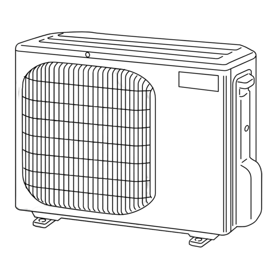
OUTDOOR UNIT
SERVICE MANUAL
Wireless type
Models
MU-GD08ND-
MU-GD10ND-
MU-GD12ND-
NOTE:
• RoHS compliant products have <G> mark on the spec name plate.
C1
C1
C1
CONTENTS
1. TECHNICAL CHANGES ···································· 2
2. PART NAMES AND FUNCTIONS ······················ 3
3. SPECIFICATION ················································· 4
4. OUTLINES AND DIMENSIONS ························· 5
5. WIRING DIAGRAM ············································ 6
6. REFRIGERANT SYSTEM DIAGRAM ················ 7
7. PERFORMANCE CURVES ································ 9
8. TROUBLESHOOTING ······································ 11
9. DISASSEMBLY INSTRUCTIONS ···················· 12
MU-GD08ND-
C1
PARTS CATALOG (TBB016)
No. TBH016
Indoor unit service manual
MS-GD•ND Series (TBH014)
TM
Advertisement
Table of Contents

Subscribe to Our Youtube Channel
Related Manuals for Mitsubishi Electric MU-GD08ND


Summary of Contents for Mitsubishi Electric MU-GD08ND
-
Page 1: Table Of Contents
SPLIT-TYPE, AIR CONDITIONERS OUTDOOR UNIT No. TBH016 SERVICE MANUAL Wireless type Models MU-GD08ND- MU-GD10ND- MU-GD12ND- Indoor unit service manual MS-GD•ND Series (TBH014) CONTENTS 1. TECHNICAL CHANGES ···································· 2 2. PART NAMES AND FUNCTIONS ······················ 3 3. SPECIFICATION ················································· 4 4. OUTLINES AND DIMENSIONS ························· 5 5. -
Page 2: Technical Changes
TECHNICAL CHANGES MU-A08ND- MU-GD08ND- 1. Compressor has been changed. (2R10S3R236A-6B = KS-098NARC) 2. Outdoor fan motor has been changed. (RA6N33-AA = RA6V21-BE) 3. Outdoor heat exchanger has been changed. 4. Compressor capacitor has been changed. 5. Fan motor capacitor has been changed. -
Page 3: Part Names And Functions
PART NAMES AND FUNCTIONS MU-C08VC MU-GD08ND MU-C10VC MU-C13VC Air inlet (back and side) Piping Drain hose Air outlet Drain outlet MU-GD10ND MU-C18VC MU-GD12ND Air inlet (back and side) Piping Drain hose Air outlet Drain outlet... -
Page 4: Specification
SPECIFICATION Outdoor model MU-GD08ND - MU-GD10ND - MU-GD12ND - Function Cooling Single phase Power supply 220-230V, 60Hz Capacity 2.2-2.2 2.9-2.9 3.6-3.6 Dehumidifi cation 0.45 K /h Air fl ow 1896-1962 1452-1524 2106-2124 Power outlet Running current (Total) 3.19-3.24 4.31-4.31 5.7-5.7... -
Page 5: Outlines And Dimensions
OUTLINES AND DIMENSIONS MU-GD08ND Unit : mm REQUIRED SPACE Basically open 100mm or more without any obstruction in front and on both sides of the unit. 381.5 Air in Air in Open two sides of left, right, or rear side. -
Page 6: Wiring Diagram
WIRING DIAGRAM MU-GD08ND MU-C08VC MU-C10VC MU-GD10ND MU-C13VC... -
Page 7: Refrigerant System Diagram
MU-GD12ND MU-C18VC REFRIGERANT SYSTEM DIAGRAM MU-GD08ND Unit : mm Refrigerant pipe 9.52 (with heat insulator) Stop valve (with service port) Outdoor Flared heat connection exchanger Compressor Strainer #100 Flared connection Capillary tube Stop valve Refrigerant pipe 6.35 (with heat insulator) - Page 8 Refrigerant piping : m Piping size O.D : mm Piping size O.D : mm Model Model Max. length Max. height Max. length Max. height Liquid Liquid MU-GD08ND - MU-GD08ND- 9.52 ø9.52 6.35 MU-GD10ND - MU-GD10ND- ø6.35 12.7 MU-GD12ND- MU-GD12ND - ø12.7...
-
Page 9: Performance Curves
PERFORMANCE CURVES MU-GD08ND MU-GD10ND MU-GD12ND MU-C08VC MU-C10VC MU-C13VC MU-C18VC The standard data contained in these specifications apply only to the operation of the air conditioner under normal conditions. Since operating conditions vary according to the areas where these units are installed. The following information has been provided to clarify the operating characteristics of the air conditioner under the conditions indicated by the performance curve. - Page 10 Air flow should be set at MAX. The unit of pressure has been changed to MPa on the international system of units(SI unit system). The conversion factor is : 1(MPa [Gauge]) =10.2(kgf/ [Gauge]) (kgf/ [Gauge])(MPa [Gauge]) MU-GD08ND MU-GD08ND 230V 220V 35( ) 35( ) Ambient temperature (˚C)/Ambient humidity (%)
-
Page 11: Troubleshooting
TROUBLESHOOTING MU-GD08ND MU-GD10ND MU-GD12ND MU-C08VC MU-C10VC MU-C13VC MU-C18VC 8-1. Cautions on troubleshooting 1. Before troubleshooting, check the following: 1) Check the power supply voltage. 2) Check the indoor/outdoor connecting wire for mis-wiring. 2. Take care of the following during servicing 1) Before servicing the air conditioner, be sure to turn OFF the main unit first with the remote controller, and then after confirming the horizontal vane is closed, turn OFF the breaker and / or disconnect the power plug. -
Page 12: Disassembly Instructions
Locking lever lever. Connector 9-1. MU-C08VC MU-C10VC MU-C13VC MU-GD08ND OPERATING PROCEDURE PHOTOS 1. Removing the cabinet Photo 1 (1) Remove the screws fixing the top panel. (See Photo 1.) Screws (2) Remove the top panel. (See Photo 1.) of the (3) Remove the screw fixing the service panel. - Page 13 OPERATING PROCEDURE PHOTOS Photo 3 2. Removing the electrical parts Outdoor fan (1) Remove the service panel and the cabinet.(Refer to 1.) capacitor (2) Remove the following parts. (C2) Lead clamp •Compressor capacitor (C1) •Outdoor fan capacitor (C2) •Terminal block (TB) •Compressor contactor (52C) NOTE : When attaching compressor contactor (52C) to relay panel, make sure that the side with...
- Page 14 OPERATING PROCEDURE PHOTOS 4. Removing the compressor (1) Remove the cabinet. (Refer to 1.) Photo 5 (2) Remove the soundproof felt. MU-C08/10VC (3) Remove the screws fixing the relay panel. (4) Remove the terminal cover. (5) Pull out the lead wires from the glass terminal of the com- Discharge pressor.
- Page 15 9-2. MU-GD10ND MU-GD12ND MU-C18VC OPERATING PROCEDURE PHOTOS Photo 1 1. Removing the cabinet (1) Remove the screws fixing the top panel. (See Photo 2 and Screws of the front panel and motor support (2) Remove the top panel. (See Photo 3.) (3) Remove the screw fixing the service panel.
- Page 16 OPERATING PROCEDURE PHOTOS MU-GD12ND Connector Outdoor fan Lead clamp capacitor (C2) Terminal block(TB1) Compressor Terminal Compressor capacitor (C1) block (TB2) contactor (52C) Photo 5 Outdoor fan motor MU-GD10ND 3. Removing propeller and the outdoor fan motor lead wires (1) Remove the cabinet. (Refer to 1.) Set screws of the Relay panel Hook...
- Page 17 OPERATING PROCEDURE PHOTOS Photo 6 4. Removing the compressor MU-GD10ND (1) Remove the cabinet. (Refer to 1.) (2) Remove the relay panel. (3) Remove the soundproof felt. Discharge pipe (4) Remove the terminal cover. Suction pipe (5) Pull out the lead wires from the glass terminal of the com- pressor.
- Page 20 HEAD OFFICE: TOKYO DENKI BLDG., 2-7-3, MARUNOUCHI, CHIYODA-KU, TOKYO100-8310, JAPAN MITSUBISHI ELECTRIC CONSUMER PRODUCTS (THAILAND) CO., LTD. New publication, effective Apr. 2008 AMATA NAKORN INDUSTRIAL ESTATE Specifications subject to change without notice. 700/406 MOO 7, TAMBON DON HUA ROH, AMPHUR MUANG, CHONBURI 20000 THAILAND...
Need help?
Do you have a question about the MU-GD08ND and is the answer not in the manual?
Questions and answers