Samsung SyncMaster 320TFT Service Manual
Color monitor
Hide thumbs
Also See for SyncMaster 320TFT:
- Service manual (8 pages) ,
- Owner's instructions manual (25 pages)

Related Manuals for Samsung SyncMaster 320TFT


Summary of Contents for Samsung SyncMaster 320TFT
-
Page 1: Table Of Contents
COLOR MONITOR SyncMaster 320TFT/520TFT SERVICE Manual COLOR MONITOR CONTENTS 1. Precautions 2. Reference Information 3. Product Specifications 4. Operating Instructions 5. Disassembly & Reassembly 6. Troubleshooting 7. Exploded View & Parts List 8. Block Diagram 9. Electrical Parts List 10. PCB Diagrams 11. - Page 2 Samsung Electronics Co., Ltd. July 1998 Printed in Korea Code No.: BN68-60012A...
-
Page 3: Precautions
Appliances), and Underwriters Laboratories (UL characteristics as the recommended replacement part Publication UL1410, 59.7). might create shock, fire and / or other hazards. Product safety is under review continuously and new instructions are issued whenever appropriate. SyncMaster 320TFT/520TFT... -
Page 4: Servicing Precautions
Use only an anti-static solder removal device. Some brushing clothes together, or lifting your foot from solder removal devices not classified as Òanti-staticÓ a carpeted floor can generate enough static can generate electrical charges sufficient to damage electricity to damage an ESD. ESDs. SyncMaster 320TFT/520TFT... -
Page 5: Reference Information
BUFFERED MICOM OUTPUT HSYNC VGAGREEN(7:0) M_HSYNC1 MICOM OUTPUT HSYNC VGARED(7:0) M_VSYNC BUFFERED MICOM OUTPUT VSYNC VGBBLUE(7:0) BLUE COLOR DATA FROM IC301 M_VSYNC1 MICOM OUTPUT VSYNC VGBGREEN(7:0) GREEN COLOR DATA FROM IC301 OSCOUT BUFFERED 24MHz CLOCK VGBRED(7:0) RED COLOR DATA FROM IC301 SyncMaster 320TFT/520TFT... - Page 6 Test Point Electrostatically Sensitive Device Underwriters Laboratories Electronic Static Field Universal Serial Bus Flyback Transformer VESA Video Electronics Standard Field Effect Transistor Association Horizontal Frequency Video Graphics Array Fail Safe Variable Registor Vertical Frequency White Balance Geometric Distortion SyncMaster 320TFT/520TFT...
-
Page 7: Product Specifications
• Headphone: Max 50mW output (3.5-pi jack) • Speaker: Internal semi Dome (8ohm x 2) • SyncMaster 320TFT/520TFT complies with SWEDAC (MPR II) recommendations for reduced electromagnetic fields. • Designs and specifications are subject to change without prior notice. SyncMaster 320TFT/520TFT... -
Page 8: Pin Assignments
GND-B GND-B GND-B No Connection No Connection Not Used GND-Sync/Self Test GND-Sync/Self Test GND-Sync/Self Test DDC Data DDC Data DDC Data H-Sync H/V-Sync Not Used V-Sync Not Used Not Used DDC Clock DDC Clock DDC Clock 16 ~26 SyncMaster 320TFT/520TFT... -
Page 9: Timing Chart
B : Horizontal sync width O : Frame time total P : Vertical sync width C : Back porch D : Active time Q : Back porch R : Active time E : Front porch S : Front porch SyncMaster 320TFT/520TFT... - Page 10 B : Horizontal sync width O : Frame time total P : Vertical sync width C : Back porch D : Active time Q : Back porch R : Active time E : Front porch S : Front porch SyncMaster 320TFT/520TFT...
-
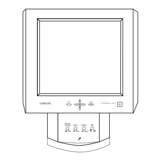
Page 11: Control And Connectors
Up / Down / + / – Buttons ON/OFF VOLUME Audio On / Off & Volume Buttons Figure 4-1. Front View and Control BASS Bass Button TREBLE Treble Button Microphone On / Off Button Microphone Amplified Stereo Speakers SyncMaster 320TFT/520TFT... -
Page 12: Operating Instructions
0 ~ 100 Menu Position 0 ~ 100 Menu Display Time 0 ~ 100 Contrast 0 ~ 100 Display Mode Color Control Color Temperature 0 ~ 100 Mode1 Green 0 ~ 100 Mode2 Blue 0 ~ 100 Mode3 SyncMaster 320TFT/520TFT... -
Page 13: Audio Controls
Decrease high sounds Increase High sounds Your LCD monitor includes an internal microphone which you can turn On or Off using the rightmost control of the Audio controls. Effect of Control Movement Function Name Audio On/Off and Volume SyncMaster 320TFT/520TFT... -
Page 14: Power Management System
DPMS software Table 4-3. Display Power Management Signaling (DPMS); 13.3” program to enable the power saving Power saving function EPA/NUTEK State function. Please contact Samsung or your Normal dealer for more information. Stand-By Suspend Mode Power Off Mode... -
Page 15: Disassembly & Reassembly
5 Disassembly and Reassembly This section of the service manual describes the disassembly and reassembly procedures for the SyncMaster 320TFT/520TFT monitors. WARNING: This monitor contains electrostatically sensitive devices. Use caution when handling these components. 5-1 Disassembly Cautions:1. Disconnect the monitor from the power source before disassembly. - Page 16 11. Remove Front Bracket Panel. 12. Disconnect jack between Panel and Inverter 2. Remove the 4 screws on the back cover of the PCB. stand and remove it. 13. Remove Rear Bracket Panel. 3. Stand the stand assembly upside down. SyncMaster 320TFT/520TFT...
- Page 17 8. Lift off the back side of the stand front 13. Remove the 2 screws on the Audio PCB of assembly and pull it toward the stand base. stand base and remove it. SyncMaster 320TFT/520TFT...
- Page 18 2. Remove a screw which is used to hold a lamp assembly on. 3. Replace lamp assemblies. 4. Assemble new lamp assembly according to the counter order. SyncMaster 320TFT/520TFT...
- Page 19 2. Remove 2 screws which are used to hold the lamp assemblies on. 3. Replace 2 lamp assemblies. 4. Assemble new lamp assemblies according to the counter order. SyncMaster 320TFT/520TFT...
- Page 20 5 Disassembly and Reassembly 5-4 Reassembly Reassembly procedures are in the reverse order of Disassembly procedures. SyncMaster 320TFT/520TFT...
-
Page 21: Troubleshooting
Does proper DC 12 V appear at Check SMPS PCB and CN816. DC jack connected to CN102? Does proper DC 5 V appear at Check F101 and IC109. Pin 3 of IC109? Check IC401, RL101, D110 and Q101. SyncMaster 320TFT/520TFT... -
Page 22: No Video
2, 3, 54, 55 and 56 of IC301? Replace IC305 or check its related circuit. Replace IC310 and IC311 or Do the waveforms appear at check its related circuits. Pins 5 and 20 of CN301? Replace LCD Panel SyncMaster 320TFT/520TFT... - Page 23 CH1 RMS = 2.35 V IC301, #55 IC301 #56 IC110 #13 IC110 #14 CH1 RMS = 200 mV CH1 RMS = 50 mV CH1 RMS = 1.24 V CH1 RMS = 400 mV IC110 #2 CH1 RMS = 4.4 V SyncMaster 320TFT/520TFT...
- Page 24 CH1 RMS = 4.3 V 6-5 User Controls Don’t Work Does the DC level change at Check the buttons. Pins 11 and 12 of IC401 when you (SW861 ~ SW866) push the front panel button? Go to 6-4 No OSD Display. SyncMaster 320TFT/520TFT...
-
Page 25: No Sound
Do the sound signals appear at Check IC803 and related circuits. Pins 3 and 14 of IC803? Does the DC 2.5 V bias appear at Check CN813, ZD803, R821, R822, Pin 16 of IC503? C815 on the Audio PCB. Check CN814, CN815 outputs. SyncMaster 320TFT/520TFT... - Page 26 Can you hear any sound from and related circuit R817, R820, the Headphones? ZD801, ZD802. Check the Headphone Plug in the Do you hear sound from the Headphone Jack and R821, R822, Internal Speaker? C815 on the Audio PCB. SyncMaster 320TFT/520TFT...
-
Page 27: Electrical Parts List
C-CERAMIC,CHIP 10nF,10%,50V,X7R,TP,2012 C131 2203-000260 C-CERAMIC,CHIP 10nF,10%,50V,X7R,TP,2012 C132 2203-000260 C-CERAMIC,CHIP 10nF,10%,50V,X7R,TP,2012 C133 2203-000260 C-CERAMIC,CHIP 10nF,10%,50V,X7R,TP,2012 C134 2203-000260 C-CERAMIC,CHIP 10nF,10%,50V,X7R,TP,2012 C135 2203-000260 C-CERAMIC,CHIP 10nF,10%,50V,X7R,TP,2012 C136 2203-000260 C-CERAMIC,CHIP 10nF,10%,50V,X7R,TP,2012 C137 2203-000203 C-CERAMIC,CHIP 100nF,10%,16V,X7R,TP,2012 C138 2203-000260 C-CERAMIC,CHIP 10nF,10%,50V,X7R,TP,2012 C139 2203-000203 C-CERAMIC,CHIP 100nF,10%,16V,X7R,TP,2012 SyncMaster 320TFT/520TFT... - Page 28 C-CERAMIC,CHIP 10nF,10%,50V,X7R,TP,2012 C183 2203-000203 C-CERAMIC,CHIP 100nF,10%,16V,X7R,TP,2012 C184 2203-000260 C-CERAMIC,CHIP 10nF,10%,50V,X7R,TP,2012 C185 2203-000203 C-CERAMIC,CHIP 100nF,10%,16V,X7R,TP,2012 C186 2404-000123 C-TA,CHIP 10uF,20%,16V,TP,6032,2.9mm C187 2404-000123 C-TA,CHIP 10uF,20%,16V,TP,6032,2.9mm C188 2203-000203 C-CERAMIC,CHIP 100nF,10%,16V,X7R,TP,2012 C189 2203-000260 C-CERAMIC,CHIP 10nF,10%,50V,X7R,TP,2012 C190 2203-000203 C-CERAMIC,CHIP 100nF,10%,16V,X7R,TP,2012 C195 2203-000260 C-CERAMIC,CHIP 10nF,10%,50V,X7R,TP,2012 SyncMaster 320TFT/520TFT...
- Page 29 C-CERAMIC,CHIP 100nF,10%,16V,X7R,TP,2012 C334 2203-000203 C-CERAMIC,CHIP 100nF,10%,16V,X7R,TP,2012 C335 2203-000203 C-CERAMIC,CHIP 100nF,10%,16V,X7R,TP,2012 C336 2203-000203 C-CERAMIC,CHIP 100nF,10%,16V,X7R,TP,2012 C337 2203-000203 C-CERAMIC,CHIP 100nF,10%,16V,X7R,TP,2012 C338 2203-000203 C-CERAMIC,CHIP 100nF,10%,16V,X7R,TP,2012 C339 2203-000203 C-CERAMIC,CHIP 100nF,10%,16V,X7R,TP,2012 C340 2203-000203 C-CERAMIC,CHIP 100nF,10%,16V,X7R,TP,2012 C341 2203-000203 C-CERAMIC,CHIP 100nF,10%,16V,X7R,TP,2012 C342 2203-000203 C-CERAMIC,CHIP 100nF,10%,16V,X7R,TP,2012 SyncMaster 320TFT/520TFT...
- Page 30 C-CERAMIC,CHIP 10nF,10%,50V,X7R,TP,2012 C383 2404-000123 C-TA,CHIP 10uF,20%,16V,TP,6032,2.9mm C384 2203-000260 C-CERAMIC,CHIP 10nF,10%,50V,X7R,TP,2012 C385 2404-000123 C-TA,CHIP 10uF,20%,16V,TP,6032,2.9mm C386 2203-000260 C-CERAMIC,CHIP 10nF,10%,50V,X7R,TP,2012 C387 2404-000123 C-TA,CHIP 10uF,20%,16V,TP,6032,2.9mm C388 2203-000260 C-CERAMIC,CHIP 10nF,10%,50V,X7R,TP,2012 C389 2203-000203 C-CERAMIC,CHIP 100nF,10%,16V,X7R,TP,2012 C390 2203-000203 C-CERAMIC,CHIP 100nF,10%,16V,X7R,TP,2012 C391 2203-000455 C-CERAMIC,CHIP 1nF,5%,50V,NPO,TP,2012 SyncMaster 320TFT/520TFT...
- Page 31 15” CN301 3711-003161 CONNECTOR-HEADER BOX,20P,1R,1.25mm,ANGLE CN301_PANEL BN39-40001K CBF-HARNESS 20P,200MM,BLK,UL2835,AWG28(2 13.3” BN39-40001J CBF-HARNESS 20P,170MM,BLK,UL2835,AWG28-20C 15” CN401 3711-001031 CONNECTOR-HEADER BOX,6P,1R,2.50mm,ANGLE CN401_CN861 BN39-40001E CBF-HARNESS 6P,280MM,BLK,UL2464,AWG24-6C D101 0401-000191 DIODE-SWITCHING MMBD4148,50V,DL-35,TP D102 0401-000191 DIODE-SWITCHING MMBD4148,50V,DL-35,TP D103 0401-000191 DIODE-SWITCHING MMBD4148,50V,DL-35,TP D104 0401-000191 DIODE-SWITCHING MMBD4148,50V,DL-35,TP SyncMaster 320TFT/520TFT...
- Page 32 FILTER-EMI SMD 25VDC,0.2A,35pF+-20%,2x FT332 2901-001113 FILTER-EMI SMD 25VDC,0.2A,35pF+-20%,2x FT333 2901-001113 FILTER-EMI SMD 25VDC,0.2A,35pF+-20%,2x FT334 2901-001113 FILTER-EMI SMD 25VDC,0.2A,35pF+-20%,2x FT335 2901-001113 FILTER-EMI SMD 25VDC,0.2A,35pF+-20%,2x FT390 2901-001114 FILTER-EMI SMD 25VDC,2.0ADC,100nF,3.2x FT404 2901-001114 FILTER-EMI SMD 25VDC,2.0ADC,100nF,3.2x IC101 1002-001099 IC-A/D CONVERTER TDA8752,8BIT,QFP,100P SyncMaster 320TFT/520TFT...
- Page 33 L301 2703-001070 INDUCTOR-SMD 100uH,10%,4.5x3.2x3.2mm L302 2703-001070 INDUCTOR-SMD 100uH,10%,4.5x3.2x3.2mm L303 2703-001070 INDUCTOR-SMD 100uH,10%,4.5x3.2x3.2mm L403 2703-001070 INDUCTOR-SMD 100uH,10%,4.5x3.2x3.2mm L406 2703-001070 INDUCTOR-SMD 100uH,10%,4.5x3.2x3.2mm L407 2703-001070 INDUCTOR-SMD 100uH,10%,4.5x3.2x3.2mm Q101 0504-000152 TR-DIGITAL KSR2101,PNP,200MW,4.7K-4.7K,S Q301 0501-000342 TR-SMALL SIGNAL KSC1623-Y,NPN,200mW,SOT- Q302 0501-000342 TR-SMALL SIGNAL KSC1623-Y,NPN,200mW,SOT- SyncMaster 320TFT/520TFT...
- Page 34 R-CHIP 100Kohm,5%,1/10W,DA,TP,2012 R309 2007-000282 R-CHIP 100Kohm,5%,1/10W,DA,TP,2012 R310 2007-000300 R-CHIP 10Kohm,5%,1/10W,DA,TP,2012 R311 2007-000282 R-CHIP 100Kohm,5%,1/10W,DA,TP,2012 R312 2007-000300 R-CHIP 10Kohm,5%,1/10W,DA,TP,2012 R316 2007-000766 R-CHIP 330ohm,5%,1/10W,DA,TP,2012 R317 2007-000572 R-CHIP 220ohm,5%,1/10W,DA,TP,2012 R401 2007-000941 R-CHIP 47Kohm,5%,1/10W,DA,TP,2012 R402 2007-000941 R-CHIP 47Kohm,5%,1/10W,DA,TP,2012 R403 2007-000941 R-CHIP 47Kohm,5%,1/10W,DA,TP,2012 SyncMaster 320TFT/520TFT...
- Page 35 R-CHIP 100ohm,5%,1/10W,DA,TP,2012 R448 2007-000290 R-CHIP 100ohm,5%,1/10W,DA,TP,2012 R449 2007-000468 R-CHIP 1Kohm,5%,1/10W,DA,TP,2012 R450 2007-000686 R-CHIP 3.3Kohm,5%,1/10W,DA,TP,2012 R451 2007-000686 R-CHIP 3.3Kohm,5%,1/10W,DA,TP,2012 R452 2007-000468 R-CHIP 1Kohm,5%,1/10W,DA,TP,2012 R455 2007-000477 R-CHIP 1Mohm,5%,1/10W,DA,TP,2012 R456 2007-000572 R-CHIP 220ohm,5%,1/10W,DA,TP,2012 R457 2007-000290 R-CHIP 100ohm,5%,1/10W,DA,TP,2012 R458 2007-000290 R-CHIP 100ohm,5%,1/10W,DA,TP,2012 SyncMaster 320TFT/520TFT...
- Page 36 2804-001217 OSCILLATOR-CLOCK 67MHz,100ppm,10TTL & CM X302 2804-001164 OSCILLATOR-CLOCK 85MHz,100ppm,10TTL(15pF X401 2801-003611 CRYSTAL-UNIT 24MHz,30ppm,28-AAA,20pF,50o ZD101 0403-000579 DIODE-ZENER BZX84C5V1,5.1V,5%,330mW,SOT- ZD102 0403-000579 DIODE-ZENER BZX84C5V1,5.1V,5%,330mW,SOT- ZD103 0403-000579 DIODE-ZENER BZX84C5V1,5.1V,5%,330mW,SOT- ZD104 0403-000579 DIODE-ZENER BZX84C5V1,5.1V,5%,330mW,SOT- ZD105 0403-000579 DIODE-ZENER BZX84C5V1,5.1V,5%,330mW,SOT- ZD401 0403-000579 DIODE-ZENER BZX84C5V1,5.1V,5%,330mW,SOT- 9-10 SyncMaster 320TFT/520TFT...
- Page 37 BOX,2P,1R,2mm,STRAIGHT,SN CN816 3711-000262 CONNECTOR-HEADER 1WALL,5P,1R,3.96mm,ANGLE,SN CN841 3711-003846 CONNECTOR-HEADER BOX,8P,1R,2mm,ANGLE,SN CN861 3711-001031 CONNECTOR-HEADER BOX,6P,1R,2.50mm,ANGLE,SN CN862 3711-000058 CONNECTOR-HEADER BOX,4P,1R,2.5mm,ANGLE,SN CN862_CN881 BN39-40001D CBF-HARNESS 4P,80MM,BLU/RED/WHT,UL1007,A CN881 3711-000058 CONNECTOR-HEADER BOX,4P,1R,2.5mm,ANGLE,SN CN882 BN39-40001F CBF-HARNESS 50MM,BLK,UL1015,AWG18,ST71 D801 0402-000016 DIODE-RECTIFIER UF5404,400V,3A,DO-201AD D802 0401-000005 DIODE-SWITCHING 1N4148,75V,150mA,500mW,4nS,DO- SyncMaster 320TFT/520TFT 9-11...
- Page 38 15V,20mA,160gf+-50gf,6x3.4mm,S SW862 3404-000243 SWITCH-TACT 15V,20mA,160gf+-50gf,6x3.4mm,S SW863 3404-000243 SWITCH-TACT 15V,20mA,160gf+-50gf,6x3.4mm,S SW864 3404-000243 SWITCH-TACT 15V,20mA,160gf+-50gf,6x3.4mm,S SW865 3404-000243 SWITCH-TACT 15V,20mA,160gf+-50gf,6x3.4mm,S SW866 3404-000243 SWITCH-TACT 15V,20mA,160gf+-50gf,6x3.4mm,S SW881 3404-000243 SWITCH-TACT 15V,20mA,160gf+-50gf,6x3.4mm,S VR841 2101-001040 VR-ROTARY 50Kohm,20%,1/30W,SIDE VR842 2101-001041 VR-ROTARY 50Kohm,20%,1/20W,TOP VR843 2101-001041 VR-ROTARY 50Kohm,20%,1/20W,TOP 9-12 SyncMaster 320TFT/520TFT...
- Page 39 9 Electrical Parts List Loc. No. Code No. Description Specification Remarks ZD801 0403-000003 DIODE-ZENER UZ8.2BL,8.2V,7.7-8.2V,500mW,DO ZD802 0403-000003 DIODE-ZENER UZ8.2BL,8.2V,7.7-8.2V,500mW,DO ZD803 0403-000003 DIODE-ZENER UZ8.2BL,8.2V,7.7-8.2V,500mW,DO ZD861 0403-000003 DIODE-ZENER UZ8.2BL,8.2V,7.7-8.2V,500mW,DO ZD862 0403-000003 DIODE-ZENER UZ8.2BL,8.2V,7.7-8.2V,500mW,DO SyncMaster 320TFT/520TFT 9-13...
- Page 40 DET,1500MM,4P/4P,IVORY,USB CABLE S/CABLE BH39-20337N CBF-SIGNAL DET,1830MM,26P/15P,IVORY,UL29 SPEAKER BN30-10001A SPEAKER-UNIT 1.5W,4ohm,84+-2db,500Hz,500 ADAPTOR BN44-30001B ADAPTOR 110V/220V,LXB520T,50HZ/60HZ,12 PROCESS-PBA UNIT BN94-30001F ASSY,PCB LXB340TTMU,ELSAT,AUSTRIA,FR-1 B/D ASS’Y CODE BN98-10001G ASSY,PCB/MAIN LXB340TTMU,ELSAT,AUSTRIA,F BN91-20001E ASSY,MAIN/AUTO-XB LXB340TTMU,AKIA,JAPAN BN91-90001C ASSY,MISC/AUTO-XB LXB530TTMU,SESAB,SWEDE BN94-20001A ASSY,LCD LXB340TTMU,SEA,13.3 BN98-90001C ASSY,PCB/MISC LXB310TTMU,SESAB,SWEDEN 9-14 SyncMaster 320TFT/520TFT...
- Page 41 8 Block Diagram SyncMaster 320TFT/520TFT...
- Page 42 9 Block Diagrams Memo SyncMaster 320TFT/520TFT...
-
Page 43: Pcb Diagrams
24LC211 IC403 S19933ADY-T1 IC309 KSR2101 Q101 LM1881M IC104 LM2596 IC107, IC108 OP881 LM2596S IC804 74F14 IC105 74F125 IC106 KA7809 IC102, IC103, IC109 LM4863 IC803 MC34067P IC110 MC141544- IC307- LT1076 IC805 DWR2 74FCT244 IC306 74FCT573M IC308 7045 IC402 SyncMaster 320TFT/520TFT 10-3... - Page 44 10 PCB Diagrams PARTS TYPE NO. REF. NO. PARTS TYPE NO. REF. NO. DS90CF561 IC310, IC311 TDA8752 IC101 GMFC1 IC301 416S1020B IC302, IC303, IC304 GMZ1 IC305 10-4 SyncMaster 320TFT/520TFT...
-
Page 45: Wiring Diagram
MIC_OUT PC_AUDIO EXT_MIC HEADPHONE SMPS PC_R_IN PC_R_IN CN101 CN101 PC_G_IN PC_G_IN PC_B_IN PC_B_IN CN102 CN103 BRIGHT S_RASTER S_RASTER BL_EN POWER PCB LCD PANEL H_SYNC H_SYNC V_SYNC V_SYNC MAIN PCB CN881 CN401 CN861 CN862 KEY2 KEY2 MAINFUNC PCB SyncMaster 320TFT/520TFT 11-1... -
Page 46: Schematic Diagrams
12 Schematic Diagrams 12-1 DAC & IO Part Schematic Diagram Power Line Signal Line 12-1 SyncMaster 320TFT/520TFT... - Page 47 IC104, #1 CH1 RMS = 3.5 V CH1 RMS = 3.1 V CH1 RMS = 4.56 V IC110 #13 IC110 #14 IC110 #2 CH1 RMS = 1.24 V CH1 RMS = 400 mV CH1 RMS = 4.4 V SyncMaster 320TFT/520TFT 12-2...
- Page 48 12 Schematic Diagrams 12-2 ZOOM & FRC Part Schematic Diagram 12 13 14 Power Line Signal Line 12-3 SyncMaster 320TFT/520TFT...
- Page 49 CH1 RMS = 2.35 V IC301, #55 IC301 #56 IC307 #12 CH1 RMS = 200 mV CH1 RMS = 50 mV CH1 RMS = 2.2 V IC307 #5 IC307 #10 CH1 RMS = 1.7 V CH1 RMS = 4.3 V SyncMaster 320TFT/520TFT 12-4...
- Page 50 9.7 mV Unit: Vrms Table 12-8. IC403 MODES 1024 x 768 / 85 Hz 4.43 4.46 4.87 5.03 Unit: Vrms Table 12-9. IC404 MODES 1024 x 768 / 85 Hz 5.03 5.03 5.03 Unit: Vrms Power Line 12-5 SyncMaster 320TFT/520TFT...
- Page 51 1024 x 768 / 85 Hz Signal (+2.5 V Bias) Signal (+2.5 V Bias) Input Signal (+2.5 V Bias) Input Signal (+2.5 V Bias) Signal (+2.5 V Bias) Signal (+2.5 V Bias) 2.5 V (Headphone : 5 V) Unit: Vrms SyncMaster 320TFT/520TFT 12-6...
- Page 52 12 Schematic Diagrams Memo 12-7 SyncMaster 320TFT/520TFT...
Need help?
Do you have a question about the SyncMaster 320TFT and is the answer not in the manual?
Questions and answers