
Related Manuals for Signal Vehicle Products SS730


Summary of Contents for Signal Vehicle Products SS730
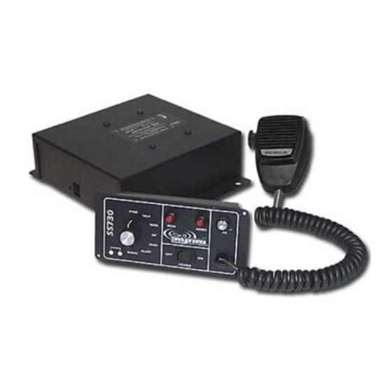
- Page 1 A Division of Star Headlight & Lantern Co., Inc. INSTALLATION AND OPERATING INSTRUCTIONS SS730 SIREN AMPLIFIER PLITSTR249 REV. C 2/5/07...
-
Page 2: Table Of Contents
Signal Vehicle Products, Inc. shall not be liable for errors contained herein or for incidental or consequential damages in connection with the furnishing, performance, or use of this manual. -
Page 3: Installation
Hands Free (HF) position. A Park Kill option is provided for connection to a door switch, etc. to disable the siren when exiting the vehicle. The PA volume control is provided on the front panel of the control head, while the Radio volume is on the amplifier box. -
Page 4: Installer-Selectable Options
INSTALLER-SELECTABLE OPTIONS The SS730 has several options that can be selected during installation. Jumpers on the back of the control head, as well as on the printed circuit board inside the amplifier case, allow the installer to select these various options. These options should be set before installation of the unit. - Page 5 Park Kill Input Polarity The Park Kill (Cutout) Input turns off any siren tone output when activated, and remains off until a control is activated or changed. The wiring diagram on page 11 shows two connection examples. The park kill input is normally activated by connecting to positive. To activate by connecting to ground (negative), move the “PKILL”...
- Page 6 Auxiliary Input Function The Auxiliary Input allows activation by an external source of either the Horn or the Manual push-button functions when the rotary selector switch is in the Manual, Alert, or Hands Free (HF) position. This input is usually wired into the vehicle horn switch.
-
Page 7: Mounting
Never operate this unit without adequate hearing protection for you and others. in the area. (OSHA 1910.95) AMPLIFIER The SS730 amplifier should be mounted in a location such as the driver compartment firewall, under the seat, or in the trunk. It is not recommended to mount the amplifier in the engine compartment or in an area that would be allowed direct exposure to weather elements. - Page 8 CONTROL HEAD Please note that for the SS741MG-TEC the 7 -position knob functions are reversed. The control head is designed to be flush mounted. Select a location such as the dash, the overhead console, or a center console. Choose a mounting location convenient to the operator and away from any air bag deployment areas.
-
Page 9: Electrical Connections
ELECTRICAL CONNECTIONS AMPLIFIER Electrical power connections to the amplifier are made using a removable connector located on the back of the amplifier case. Communication between the control head and the amplifier are made via a special communication cable. CAUTION: Please note that this cable IS NOT a standard telephone cord and CANNOT be replaced with one. - Page 10 Wire Size and Termination The wiring diagram on the next page shows the minimum wire size used for each connection, along with recommended lead color. Please use the following guidelines when wiring your siren: • If the wire is longer than 10 ft. use the next larger wire size. Use only high quality crimp connectors.
- Page 11 -10-...
-
Page 12: Operation
OPERATION GENERAL Please note that for the SS741MG-TEC the 7 -position knob functions are reversed. This unit is designed for easy operation under the stress associated with high-speed pursuit. Most siren functions are accessible with one simple motion without repetitive activation of switches or automatic timed switching that can interfere with desired operation. -
Page 13: Selector Switch
SELECTOR SWITCH The rotary selector switch controls the primary operating function of the siren. PSHR (Phaser)- Ultra-fast warble tone used for maximum attention in highly congested areas. YELP - A rapid warble tone used in light to moderately congested areas . Please note that for the WAIL - A normal rise-fall tone used on highways and SS741MG-TEC the 7 -position... -
Page 14: Horn
With the selector switch in the Manual, Alert or Hands Free position this momentary push-button switch provides a manually activated Wail siren tone. While the selector switch is in the Wail, Yelp, or Phaser position, this switch provides a generally quicker changing tone. (See tables below and on next page). These quicker tones are used to momentarily alert motorists at intersections and very highly congested areas. -
Page 15: Volume Controls
VOLUME CONTROLS RADIO REPEAT VOLUME The radio repeat volume is recessed on the front face of the amplifier next to the communication jack. This should be set when the vehicle is parked. First set the volume level of the vehicle’s two-way radio to its normal operating volume. -
Page 16: Service
TROUBLESHOOTING Symptom Possible Cause Check No power Power switch not turned on Does back-lighting come on? Connector loose Do you hear a “pop” when turned on? Amplifier 20A fuse blown Is power hooked up backwards? Positive ground vehicle? Is an external fuse or circuit breaker used? Loose connection at power source Are the negative leads connected to a good ground? -
Page 17: Rfi Reduction
If you are experiencing an unusually high amount of RFI, you may perform the following steps to help reduce the RFI: Make sure that both the control head and amp are securely attached to good chassis ground (i.e. no paint in-between the chassis and the grounding terminal). -
Page 18: Parts
CANNOT be replaced with one. LIMITED WARRANTY Signal Vehicle Products warrants this new product to be free from defects in material and workmanship, under normal use and service, for a period of one (1) year from the date of delivery to the first user-purchaser. -
Page 19: Specifications
SPECIFICATIONS Input Voltage 10 - 16 VDC (negative ground) Input Current 8.0 Amps @ 13.6 VDC (single 100W speaker) 16 Amps @ 13.6 VDC (dual 100W speakers) Standby Current Less than 150 mA Audio Frequency 200Hz - 10 kHz + 3db Audio Output 40 watts @13.6 VDC (single 100W speaker) Output Power... -
Page 20: Control Head Cut-Out Installation Template
-19-...
Need help?
Do you have a question about the SS730 and is the answer not in the manual?
Questions and answers