
Related Manuals for Signal Vehicle Products SS741MG


Summary of Contents for Signal Vehicle Products SS741MG
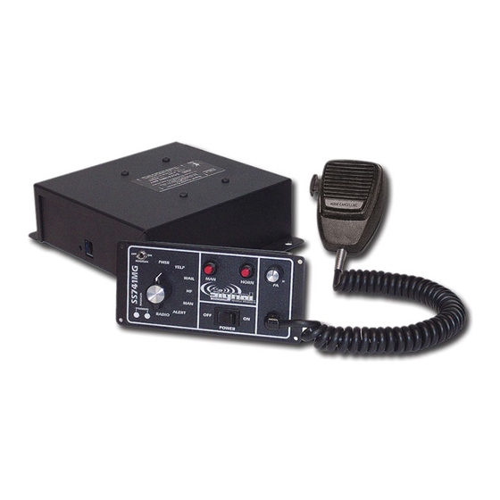
- Page 1 A Division of Star Headlight & Lantern Co., Inc. INSTALLATION AND OPERATING INSTRUCTIONS SS741MG SIREN AMPLIFIER PLITSTR250 REV E 1/16/08...
-
Page 2: Table Of Contents
Due to continuous product improvements, we must reserve the right to change any specifications and information contained in this manual at any time without notice. Signal Vehicle Products, Inc. makes no warranty of any kind with regard to this manual, including, but not limited to, the implied warranties of merchantability and fitness for a particular purpose. -
Page 3: Installation
Another feature allows cycling through Wail, Yelp, Phaser and Standby by providing a signal to the horn ring auxiliary wire when the function switch is in the Hands Free (HF) position. A Park Kill option is provided for connection to a door switch, etc. -
Page 4: Installer-Selectable Options
INSTALLER-SELECTABLE OPTIONS The SS741MG has several options that can be selected during installation. Jumpers on the back of the control head, as well as on the printed circuit board inside the amplifier case, allow the installer to select these various options. These options should be set before installation of the unit. - Page 5 Park Ki ll Input Polarity - The Park Kill (Cutout) Input turns off any siren tone output when activated, and remains off until a control is activated or changed. The wiring diagram on page 10 shows two connection examples. Connecting to positive normally activates the park kill input. To activate by connecting to ground (negative), move the “PKILL”...
- Page 6 Phaser Disable The Phaser function can be completely disabled by removing the second option jumper from the back of the control head. This will also disable the Two-Tone function used when the manual button (MAN) is pressed while the mode switch is in the Phaser position (PHSR).
-
Page 7: Mounting
Never operate this unit without adequate hearing protection for you and others. in the area. (OSHA 1910.95) AMPLIFIER The SS741MG amplifier should be mounted in a location such as the driver compartment firewall, under the seat, or in the trunk. It is not recommended... - Page 8 Please note that for the SS741MG-TEC the 7 -position knob functions are reversed. from any air bag deployment areas. Be sure to choose a location that has at least two inches of depth to accommodate the control head and cables.
-
Page 9: Electrical Connections
ELECTRICAL CONNECTIONS AMPLIFIER Electrical power connections to the amplifier are made using a removable connector located on the back of the amplifier case. Communication between the control head and the amplifier are made via a special communication cable. CAUTION: Please note that this cable IS NOT a standard telephone cord and CANNOT be replaced with one. - Page 10 Wire Size and Termination The wiring diagram on the next page shows the minimum wire size used for each connection, along with recommended lead color. Please use the following guidelines when wiring your siren: • If the wire is longer than 10 ft. use the next larger wire size. Use only high quality crimp connectors.
-
Page 11: Wiring Diagram
8 - White (#18 AWG) 6 - Blue (#18 AWG) 3 - Blue (#18 AWG) 2 and 5 - Black 1 and 4 - Red -10-... -
Page 12: Operation
OPERATION Please note that for the SS741MG-TEC the 7 -position knob functions are reversed. GENERAL This unit is designed for easy operation under the stress associated with high-speed pursuit. Most siren functions are accessible with one simple motion without repetitive activation of switches or automatic timed switching that can interfere with desired operation. -
Page 13: Horn
HORN (Air Horn) This momentary push-button switch provides a simulated air-horn tone while pressed. This can be used to either replace, or to supplement the normal vehicle horn and is useful at intersections or in low noise areas. This tone will override all other siren tones. -
Page 14: Magnum Mode
Magnum Mode: Rotary Switch Speakers Pressing Manual Pushbutton Position: 1 / 2 1 / 2 Phaser Wail/Phaser Wail/Two-Tone Yelp Double Yelp Yelp/Phaser (Staggered) Wail Double Wail Wail/Yelp (Staggered) Creates two staggered manual WAIL Hands Free No Output tones while button is being held that sweep down when the button is released. -
Page 15: Volume Controls
VOLUME CONTROLS Radio Repeat Volume - The radio repeat volume is recessed on the front face of the amplifier next to the communication jack. This should be set when the vehicle is parked. First set the volume level o f the vehicle’s two-way radio to its normal operating volume. -
Page 16: Service
TROUBLESHOOTING Symptom Possible Cause Check No power Power switch not turned on Does back-lighting come on? Connector loose Do you hear a “pop” when turned on? Amplifier 15A fuse blown Is power hooked up backwards? Positive ground (one or both) vehicle? Is an external fuse or circuit breaker used? Loose connection at power source... -
Page 17: Rfi Reduction
If you are experiencing an unusually high amount of RFI, you may perform the following steps to help reduce the RFI: Make sure that both the control head and amp are securely attached to good chassis ground (i.e. no paint in-between the chassis and the grounding terminal). -
Page 18: Parts
During this warranty period the obligation of Signal Vehicle Products is limited to repairing or replacing, as Signal Vehicle Products may elect, any part or parts of such product which after examination by Signal Vehicle Products is determined to be defective in material and/or workmanship. -
Page 19: Specifications
SPECIFICATIONS Input Voltage 10 - 16 VDC (negative ground) Input Current 16 Amps @ 13.6 VDC (dual 100W speakers) Standby Current Less than 150 mA Audio Frequency 200Hz - 10 kHz + 3db Audio Output 40 watts @13.6 VDC (single 100W speaker) Output Power 105 WATTS RMS MAX. -
Page 20: Control Head Cut-Out Installation Template
-19-...
Need help?
Do you have a question about the SS741MG and is the answer not in the manual?
Questions and answers