
Related Manuals for NewMar 24-1000RM


Summary of Contents for NewMar 24-1000RM
- Page 1 INSTALLATION & OPERATION MANUAL MODELS: 24-1000RM 48-1000RM 48-1000IRM 48-2000RM 48-2000IRM 125-1000RM 125-2000RM Newmar 2911 W. Garry Ave Santa Ana, CA 92704 Tel: 714.751.0488 Fax: 714.957.1621 As of 8-11...
-
Page 2: Table Of Contents
ONTACT OMMUNICATION ERMINAL 7-2 SNMP E (WEB) ........16 XPANSION 7-3 RS-232 C (GUI) ........16 OMMUNICATION 8. TECHNICAL SPECIFICATIONS ......... 17 24-1000RM ………………………………………………………...19 48-1000RM ………………………………………………………...20 48-2000RM…………………………………………………………21 125-1000RM………………………………………………………..22 125-2000RM ..................48-1000IRM ..................48-2000IRM ..................MPXXXNX02ABX ..........24 RAWING 9. OPTIONAL HARDWARE: ..........25... -
Page 3: Introduction
1. INTRODUCTION 1-1 General Information Thank you for choosing NEWMAR as the power products supplier to your company. NEWMAR’s Rackmount Pure Sine Wave Power Inverters are designed and built for full reliability at multiple locations and variety of applications. These intelligent, dependable inverters provide economical AC Power for all your network needs. -
Page 4: Symbols
Do not operate near water or in excessive humidity. Keep liquid and foreign objects from entering the inverter. Install the inverter in a well-ventilated area. Do not block front air vents, or rear air exhausts of the unit. Do not operate the inverter close to combustible gas or open fire. Do not plug appliances with surging loads, or half bridge rectified loads, into the inverter. -
Page 5: Block Diagram
Advanced Protection Features: Input reverse polarity-proof protection Internal over temperature protection Output overload protection Output over/under voltage protection Output short circuit protection DC input short circuit protection: fuse and breaker AC input short circuit protection: breaker Input over/under voltage protection Fan failure detection and protection 3-2 Block Diagram Rackmount Pure Sine Wave Inverter Block Diagram... -
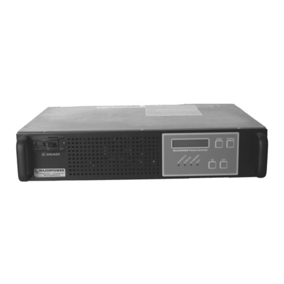
Page 6: Rear Panel
ON/OFF buttons: These are the two power buttons for turning on or turning off the inverter. Once the inverter is on, the “ON” button works as the On-Line <=> Off-Line mode switching button. INVERTER ON Indicates the INVERTER has been turned on and is working normally (output is available to support load equipment). -
Page 7: Bypass Switching And Grounding
AC Input Terminal Terminal for bypass VAC input voltage. A 115 VAC, 20 amp circuit is recommended for full power operation. AC Input Breaker Breaker for AC input DC Input Terminal Terminal for VDC input voltage Dry Contact Terminal Dry contact terminal is connected to two Form C relays. One is for “DC abnormal” and the other one is for “FAULT”. -
Page 8: Installation Tool Kit
Connect the DC input voltage cables before engaging the front panel DC breaker. Use the following recommended cable sizes when connecting power to the inverter. Model Capacity DC Input AC Input AC Output 24-1000RM 1 KVA #6 AWG #12 AWG NEMA 5-15R... -
Page 9: Front Panel Operation Of Sequence (Software Version 0.0 Or 3.1)
Only two hardwire adapters will fit on the integrated NEMA duplex outlets of the inverter. Loads should be distributed so not to exceed current ratings of hardware and cable. 5-3 Front Panel Operation of Sequence (Software Version 0.0 or 3.1) 1. -
Page 10: Data" Button
5-4 “DATA” button You can use the "DATA" button to select the following information which is displayed on the LCD screen: A) Output voltage: Shows present output voltage. OUTPUT VOLT. *** □□□.□V *** B) Inverter voltage: Shows present “inverter” voltage. INVERTER VOLT. -
Page 11: Status" Button
OUTPUT VA *** □□□□ VA *** I) Output power: Shows present output power (Watt) OUTPUT POWER *** □□□□ W *** J) Temperature: Shows the temperature inside the INVERTER TEMPERATURE *** □□.□ º C *** K) Firmware Version: Shows the CPU firmware version FIRMWARE VERSION *** V □.□... - Page 12 B) DC to AC inverter status When the INVERTER is normal, LCD shows ** INVERTER ** NORMAL b) When the inverter is over temperature (may be caused by overload, high ambient temperature or fan failure), LCD shows. ** INVERTER ** OVER TEMPERATURE c) When the temperature inside the INVERTER is too high, LCD shows.
- Page 13 ** BYPASS AC ** NORMAL b) When the input bypass voltage is normal and INVERTER output is in “bypass mode”, LCD shows INVERTER : STD BY BYPASS : ON c) When the input bypass voltage is “too low”, LCD shows. ** BYPASS AC ** UNDER VOLTAGE d) When the input bypass voltage is “too high”, LCD shows.
-
Page 14: Error Message
DC UNDER VOLT INVERTER OFF e) When the input DC voltage is over voltage, INVERTER will switch to bypass mode (if bypass AC is available) and LCD shows. DC OVER VOLT INVERTER OFF 5-6 Error message If the following messages appear on the LCD screen, contact Majorpower at once. ** INVERTER ** SOFTSTART FAIL EEPROM... -
Page 15: Troubleshooting
6-2 Troubleshooting Problem Possible cause Action to take *NOTE - If utility by-pass is not being used, and AC input is not present, the fault LED will Turn on or reset the The circuit breaker is “off” circuit breaker. remain on. DC cable polarity Apply correct DC LEDs do not light up... -
Page 16: Communication
O/P = 208Vac O/P = 220Vac O/P = 230Vac O/P = 240Vac AC Bypass Voltage 200Vac 210Vac 220Vac Range 188Vac ~228Vac ~240Vac ~250Vac ~257Vac AC Bypass Frequency Range F=50Hz 45.5Hz ~ 54.5Hz AC Bypass Frequency Range F=60Hz 55.5Hz ~ 64.5Hz AC Bypass Recovery From Over Voltage 223Vac... -
Page 17: Technical Specifications
PIN4 (PNP) PIN5 (COMMON) --------------- PIN5 (COMMON) PIN6 (PNP) ------------------ PIN6 (PNP) PIN7 (PNP) ------------------ PIN7 (PNP) 8. TECHNICAL SPECIFICATIONS 24-1000RM DC Input Voltage 20-30 VDC Rated Current 50 Amps Protection Fuse and DC Breaker Efficiency >85% (full linear load),... -
Page 18: 48-1000Rm
48-1000RM DC Input Voltage 40-60 VDC Rated Current 25 Amps Protection Fuse and DC Breaker Efficiency >85% (full linear load), 48 VDC I/P, 120 VAC O/P AC Output Capacity 1KVA / 800W Voltage 100, 110, 115, 120 VAC Voltage Regulation ±2% Frequency 50/60Hz ±... -
Page 19: 48-2000Rm
48-2000RM DC Input Voltage 40-60 VDC Rated Current 50 Amps Protection Fuse and DC Breaker Efficiency >85% (full linear load), 48 VDC I/P, 120 VAC O/P AC Output Capacity 2KVA / 1600W Voltage 100, 110, 115, 120 VAC Voltage Regulation ±2% Frequency 50/60Hz ±... -
Page 20: 125-1000Rm
125-1000RM DC Input Voltage 100-150 VDC Rated Current 10 Amps Protection Fuse and DC Breaker Efficiency >85% (full linear load), 125 VDC I/P, 120 VAC O/P AC Output Capacity 1KVA / 800W Voltage 100, 110, 115, 120 VAC Voltage Regulation ±2% Frequency 50/60Hz ±... -
Page 21: 125-2000Rm
125-2000RM DC Input Voltage 100-150 VDC Rated Current 20 Amps Protection Fuse and DC Breaker Efficiency >85% (full linear load), 125 VDC I/P, 120 VAC O/P AC Output Capacity 2KVA / 1600W Voltage 100, 110, 115, 120 VAC Voltage Regulation ±2% Frequency 50/60Hz ±... -
Page 22: 48-1000Irm
48-1000IRM DC Input Voltage 40-60 VDC Rated Current 25 Amps Protection Fuse and DC Breaker Efficiency >85% (full linear load), 48 VDC I/P, 230 VAC O/P AC Output Capacity 1KVA / 800W Voltage 208, 220, 230, 240 VAC Voltage Regulation ±2% Frequency 50/60Hz ±... -
Page 23: 48-2000Irm
48-2000IRM DC Input Voltage 40-60 VDC Rated Current 50 Amps Protection Fuse and DC Breaker Efficiency >85% (full linear load), 48 VDC I/P, 230 VAC O/P AC Output Capacity 2KVA / 1600W Voltage 208, 220, 230, 240 VAC Voltage Regulation ±2% Frequency 50/60Hz ±... -
Page 24: Drawing No. Mpxxxnx02Abx
Drawing No. MPXXXNX02ABX Page 24... -
Page 25: Optional Hardware
9. Optional Hardware: SNMP Remote Communication Card: Remote monitoring is a prime consideration and requirement to manage multiple network elements from a central location. Remote access is established by simply installing the plug-n-play card, configuring your network IP address, and attaching the network interface cable. Locking - Hardwire Adapter: Reliable locking NEMA 5-15 plug to secure load circuits to the output sockets of the inverter.
Need help?
Do you have a question about the 24-1000RM and is the answer not in the manual?
Questions and answers