Advertisement
Quick Links
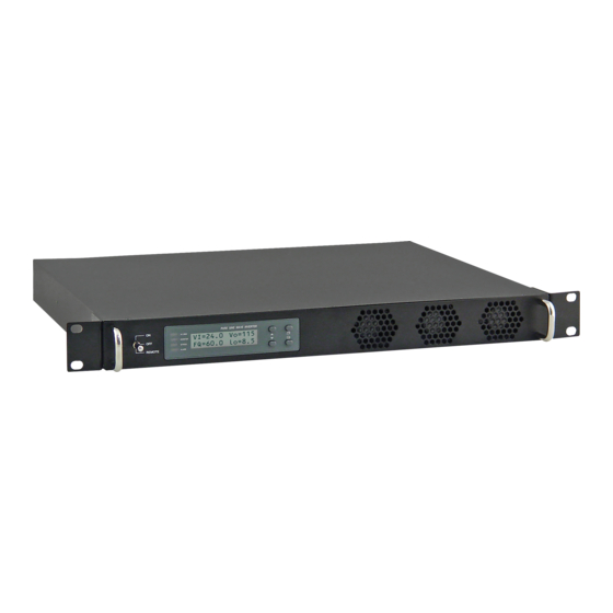
48-1U-1000RM
Pure Sine Wave Inverter
User's Manual
Table of Contents
Page
1. Important Safety Instructions........................................... ........................................................ 1
2. Introduction to Functional Characteristics.................................. ....................................................... 1
3. Installation and Maintenance................................................. ......................................................... 5
4. Operation.................................................................................. ......................................................... 10
5 Front LCD Panel Display and Setup........................................................................................................... 10
6. RS232 Communication and Operation.............................. ........................................................... 17
7. Information...................... ....................................................................................................... 19
Advertisement

Subscribe to Our Youtube Channel
Related Manuals for NewMar 48-1U-1000RM


Summary of Contents for NewMar 48-1U-1000RM
-
Page 1: Table Of Contents
48-1U-1000RM Pure Sine Wave Inverter User’s Manual Table of Contents Page 1. Important Safety Instructions……………………………………............1 2. Introduction to Functional Characteristics……………………………............1 3. Installation and Maintenance…………………………………………............5 4. Operation………………………………………………………………………............10 5 Front LCD Panel Display and Setup……………………………………….............. 10 6. -
Page 2: Important Safety Instructions
WARNING! Before using the Inverter, read and save the safety instructions. 1-1-1. 1-1-2. 1-1-3. 1-1-4. 1-2. Other Safety Notes 1-2-1. 1-2-2. 1-2-3. 1-2-4. 1-2-5. 1-2-6. 1-2-7. 1-2-8. 1-2-9. 1-2-10. 1-2-11. 1-2-12. 2. Functional Characteristics Introduction 2-1. - Page 3 2-2 Block Diagram AC GRID FILTER INPUT BYPASS RELAY INPUT FILTER OUTPUT...
- Page 4 Electrical Specification Model No. Item 24-1U-1000 48-1U-1000 24-1U-1000F 48-1U-1000F Input Characteristics Output Characteristics Signal and Control Protection Bypass Relay Operating Temperature Fan Operation and Indicator Mechanical Specification Safety and EMS...
- Page 5 2-4 Mechanical Drawings 1U Series Inverter Ordering Information Model Input Output Voltage Output Voltage Frequency Number Voltage Nominal Range Range...
-
Page 6: Installation And Maintenance
3. Installation and Maintenance 3.1 Rear Panel Rear Panel View IEC Version Remote DC Input DC Input Standard AC Input AC Input Control Contact RS-232 Output Control RS-232 Negative (-) Positive (+) Contact Output Socket Socket Breaker Breaker Negative (-) Positive (+) Terminal Terminal Sockets... - Page 7 3-1-3. Wire Color Wire Length / Socket Gauge 120 VAC 230 VAC 3-1-4. 3-1-5. 3-1-6. Pg. 6...
- Page 8 NOTE: Contact Rating Operating / Maximum Number of Load Storage Voltage Operations N.O. N.C. Temperature...
- Page 9 Dry Contact Terminal Relay 3-1-7. Model No. Wire AWG Inline Fuse WARNING!
- Page 10 WARNING! 3-3. Front Panel Front Panel View Main Switch Fan Ventilator 3-3-1. 3-3-2. 3-3-3. 3-3-4.
-
Page 11: Operation
3-4. Maintenance 3-4-1. 3-4-2. 3-4-3. 3-4-4. 3-4-5. 4. Operation: 4-1. Connecting the input power 4-2. Connecting the loads 4-3. Inverter Operation 4-4 Protective Features DC Input (VDC) Over Temperature Protection Over Voltage Under Under Voltage INTERIOR HEAT SINK Model Voltage Shut-down Restart Shut-down... - Page 12 5-1-2. LED Indications: • AC GRID: AC Input LED Status DC-AC Inverter LED Status Bypass LED Status AC Output (Load) Alarm LED Status 5-1-3.
- Page 13 5-1-4. 5-2. Startup Sequence and Standby Status 5-2-1.
- Page 14 5-3. Setup Menu – Operation and Instructions Entering Setup Menu: 5-3-1. LCD Contrast: LCD Auto-off: RS232 Baud-rate:...
- Page 15 Buzzer Setting: Menu Status Buzzer Alert Setup: Menu Status Relay 5-3-2. OVP Setting: Model Setting Value Range OVP Recovery: Model Setting Value Range UVP Setting: Model Setting Value Range...
- Page 16 UVP Recovery: Model Setting Value Range UV Alarm: Model Setting Value Range 5-3-3. O/P Voltage: Model Setting Value Range O/P Frequency: Model Setting Value Range Sync Frequency: Model Setting Value Range...
- Page 17 Bypass Relay: Bypass Relay Mode Menu Switching Feature Overload Alarm:...
-
Page 18: Rs232 Communication And Operation
6. RS-232 Communication and Operation 6-1. 6-1-1. Signal Description 6-1-2. 6-1-3. 6-1-4. - Page 19 6-2. Interface Commands: 6-2-1. 6-3. Example of the RS232 Operation: 6-3- 6-3-2...
- Page 20 6-3-3. <Function Code> Setting Menu <Function Code> Setting Menu FUNC 0: Setting Menu SETT <value> FUNC 1: Setting Menu SETT <value> FUNC 2: Setting Menu SETT <value> Baud rate...
- Page 21 FUNC 3: Setting Menu SETT <value> Buzzer (Beep sound) FUNC 4: Setting Menu SETT <value> Alert FUNC 6: Setting Menu SETT <value> Model FUNC 7: Setting Menu SETT <value> Model FUNC 8: Setting Menu SETT <value> Model...
- Page 22 FUNC 9: Setting Menu SETT <value> Model FUNC 10: Setting Menu SETT <value> Model FUNC 11: Setting Menu SETT <value> Model FUNC 12: Setting Menu SETT <value> FUNC 13: Setting Menu SETT <value> FUNC 14: Setting Menu SETT <value> Model...
-
Page 23: Information
FUNC 14: Setting Menu SETT <value> WARNING! Do not open or disassemble the 1U series Inverter. Attempting to service the unit may cause risk of electrical shock or fire. Problems and Symptoms Possible Cause Solutions No AC Power “Output” 6. Warranty and Contact Information...
Need help?
Do you have a question about the 48-1U-1000RM and is the answer not in the manual?
Questions and answers