Pioneer M-IS21 Service Manual
Hide thumbs
Also See for M-IS21:
- Service manual (46 pages) ,
- Operating instructions manual (57 pages) ,
- Operating instructions manual (56 pages)
Table of Contents
Advertisement
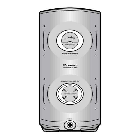
STEREO POWER AMPLIFIER
M-IS21
THIS MANUAL IS APPLICABLE TO THE FOLLOWING MODEL(S) AND TYPE(S).
Model
Type
M-IS21
KUCXJ
This product is a component of a system.
For the accessories, instruction manuals etc., refer to the service manuals RRV2149 for
XC-IS21MD and RRV2148 for XC-IS21T.
This product does not function properly when independent; to avoid malfunctions, be
sure to connect it to the prescribed system component(s), otherwise damage may
result.
Component
CD MD TUNER
CD TUNER DECK
STEREO POWER AMPLIFIER
SPEAKER SYSTEM
CONTENTS
1. SAFETY INFORMATION ...................................... 2
2. EXPLODED VIEWS AND PARTS LIST ................ 3
3. SCHEMATIC DIAGRAM ....................................... 6
4. PCB CONNECTION DIAGRAM ............................ 8
5. PCB PARTS LIST ............................................... 14
6. ADJUSTMENT .................................................... 16
PIONEER ELECTRONIC CORPORATION
PIONEER ELECTRONICS SERVICE, INC. P.O. Box 1760, Long Beach, CA 90801-1760, U.S.A.
PIONEER ELECTRONIC (EUROPE) N.V. Haven 1087, Keetberglaan 1, 9120 Melsele, Belgium
PIONEER ELECTRONICS ASIACENTRE PTE. LTD. 253 Alexandra Road, #04-01, Singapore 159936
PIONEER ELECTRONIC CORPORATION 1999
Power Requirement
AC120V
System
IS-21MD
IS-21T
XC-IS21MD
–––
XC-IS21T
M-IS21
M-IS21
S-IS21
S-IS21
4-1, Meguro 1-Chome, Meguro-ku, Tokyo 153-8654, Japan
Service Manual
–––
RRV2149
RRV2148
RRV2143
RRV2141
7. GENERAL INFORMATION ................................ 17
7.1 SINGLE OPERATION METHOD ................. 17
8. PANEL FACILITIES AND SPECIFICATIONS .... 18
ORDER NO.
RRV2143
Remarks
Remarks
This Service Manual
T – ZZK MAY. 1999 Printed in Japan
Advertisement
Table of Contents

Related Manuals for Pioneer M-IS21


Summary of Contents for Pioneer M-IS21
- Page 1 PIONEER ELECTRONIC CORPORATION 4-1, Meguro 1-Chome, Meguro-ku, Tokyo 153-8654, Japan PIONEER ELECTRONICS SERVICE, INC. P.O. Box 1760, Long Beach, CA 90801-1760, U.S.A. PIONEER ELECTRONIC (EUROPE) N.V. Haven 1087, Keetberglaan 1, 9120 Melsele, Belgium PIONEER ELECTRONICS ASIACENTRE PTE. LTD. 253 Alexandra Road, #04-01, Singapore 159936 PIONEER ELECTRONIC CORPORATION 1999 T –...
- Page 2 , a l w a y s c o n s u l t t h e c u r r e n t P I O N E E R Service Manual. A subscription to, or additional copies Also test with plug reversed of, PIONEER Service Manual may be obtained at a (Using AC adapter Earth nominal charge from PIONEER.
- Page 3 M-IS21 2. EXPLODED VIEWS AND PARTS LIST NOTES: Parts marked by "NSP" are generally unavailable because they are not in our Master Spare Parts List. mark found on some component parts indicates the importance of the safety factor of the part.
- Page 4 M-IS21 2.2 EXTERIOR...
- Page 5 M-IS21 Caution when disassemble. Even if the power supply code is pulled out from the outlet, neither C11 nor C12 of AF ASSY are discharged. Please discharge C11 and C12 of AF ASSY by the resistor of 100 Ω or more before removing AF ASSY or POWER SUPPLY ASSY.
- Page 6 M-IS21 3. SCHEMATIC DIAGRAM 3.1 AF, AMP, POWER SUPPLY, PRIMARY, SECONDARY, HP, METER and METER CONNECT ASSYS AMP ASSY (AWU7342) POWER SUPPLY ASSY (AWU7344)
-
Page 7: Primary Assy
M-IS21 Note : When ordering service parts, be sure to refer to "EXPLODED CAUTION : FOR CONTINUED PROTECTION AGAINST RISK OF FIRE, REPLACE ONLY WITH SAME TYPE NO. 491002F, MFD BY VIEWS and PARTS LIST" or "PCB PARTS LIST" LITTELFUSE INK. FOR IC42 (AEK7067). -
Page 8: Primary And Secondary Assys
M-IS21 4. PCB CONNECTION DIAGRAM NOTE FOR PCB DIAGRAMS: 1. Part numbers in PCB diagrams match those in the schematic 3. The parts mounted on this PCB include all necessary parts diagrams. for several destination. 2. A comparison between the main parts of PCB and schematic For further information for respective destinations, be sure diagrams is shown below. - Page 9 M-IS21 4.2 HP, METER and METER CONNECT ASSYS METER CONNECT ASSY HP ASSY METER ASSY CN3105 CN3104 (ANP7300-C) SIDE A POWER METER METER ASSY HP ASSY Q5604 IC5601 Q5601 Q5602 METER Q5603 CONNECT ASSY (ANP7300-C) SIDE B...
- Page 10 M-IS21 4.3 AF ASSY CN3006 IC3302 CN3003 J3004 CN3002 J3005 IC82 IC81 3001 ASSY L BROWN N BLUE NEUTRAL AC IN LIVE SIDE A (ANP7300-C)
- Page 11 M-IS21 Q3313 Q3602 ASSY SIDE B Q3603 Q3601 Q3607 Q3608 Q3606 Q3605 (ANP7300-C) Q3621...
- Page 12 M-IS21 4.4 AMP and POWER SUPPLY ASSYS IC24 IC23 POWER SUPPLY ASSY Q3651 Q3654 IC33 IC42 CN3102 CN3106 CN3103 Q3502 Q3501 ASSY IC3301 SIDE A (ANP7300-C) Q3352 Q3351...
- Page 13 M-IS21 POWER SUPPLY IC32 ASSY Q3652 Q3653 Q3311 ASSY Q3312 Q3503 IC3502 IC3501 Q3353 Q3354 SIDE B (ANP7300-C)
- Page 14 M-IS21 5. PCB PARTS LIST NOTES: Parts marked by "NSP" are generally unavailable because they are not in our Master Spare Parts List. mark found on some component parts indicates the importance of the safety factor of the part. Therefore, when replacing, be sure to use parts of identical designation.
- Page 15 M-IS21 Mark No. Description Part No. Mark No. Description Part No. D3351–D3354, D3361, D3362 1SS133 RESISTORS D3355, D3356 LT2A03 RD1/2LMF121J D3357, D3358 MTZJ10C RD1/2LMF910J D3359, D3360 MTZJ18B R3659 RD1/2PM330J D3363, D3364 MTZJ39C Other Resistors RS1/10S CAPACITORS OTHERS C3319, C3320 CCSQCH100D50...
- Page 16 M-IS21 Mark No. Description Part No. 6. ADJUSTMENT There is no information to be shown in this chapter. OTHERS 5601 3P CABLE HOLDER 51048-0300 3005 4P CABLE HOLDER 51048-0400 J3005 4P JUMPER WIRE D20PYY0410E METER CONNECT ASSY SEMICONDUCTORS D5603 MTZJ5.6C...
- Page 17 M-IS21 7. GENERAL INFORMATION 7.1 SINGLE OPERATION METHOD Single operation method and inputlevel. The procedure and the input level of a single operation are shown below. 1. R85 are shorted by 1kΩ. 2. A point of the figure below in four places is connected.
-
Page 18: Panel Facilities And Specifications
M-IS21 8. PANEL FACILITIES AND SPECIFICATIONS ¶ PANEL FACILITIES ¶ SPECIFICATIONS 7 Amplifier Section Continuous average power output of 55 watts* per channel, min., at 6 ohms, from 60 Hz to 15,000 Hz with no more than 1.0 %** total harmonic dis- tortion. -
Page 19: Table Of Contents
PIONEER ELECTRONIC CORPORATION 4-1, Meguro 1-Chome, Meguro-ku, Tokyo 153-8654, Japan PIONEER ELECTRONICS SERVICE, INC. P.O. Box 1760, Long Beach, CA 90801-1760, U.S.A. PIONEER ELECTRONIC (EUROPE) N.V. Haven 1087, Keetberglaan 1, 9120 Melsele, Belgium PIONEER ELECTRONICS ASIACENTRE PTE. LTD. 253 Alexandra Road, #04-01, Singapore 159936 PIONEER ELECTRONIC CORPORATION 1999 T –... -
Page 20: Safety Information
, a l w a y s c o n s u l t t h e c u r r e n t P I O N E E R Service Manual. A subscription to, or additional copies Also test with plug reversed of, PIONEER Service Manual may be obtained at a (Using AC adapter Earth nominal charge from PIONEER. -
Page 21: Exploded Views And Parts List
M-IS21 2. EXPLODED VIEWS AND PARTS LIST NOTES: Parts marked by "NSP" are generally unavailable because they are not in our Master Spare Parts List. mark found on some component parts indicates the importance of the safety factor of the part. - Page 22 M-IS21 2.2 EXTERIOR...
- Page 23 AMR7006 BIND Assy AWU7349 Lens Holder A AMR7245 Refrector AMR7248 (2) CONTRAST TABLE M-IS21/MYXJ and NVXJ are constructed the same except for the following : Part No. Mark No. Symbol and Description Remarks MYXJ Type NVXJ Type Rear Panel ANC7823...
-
Page 24: Schematic Diagram
M-IS21 3. SCHEMATIC DIAGRAM 3.1 AF, AMP, POWER SUPPLY, PRIMARY, SECONDARY, HP, METER and METER CONNECT ASSYS AMP ASSY (AWU7340) POWER SUPPLY ASSY (AWU7344) - Page 25 M-IS21 Note : When ordering service parts, be sure to refer to "EXPLODED CAUTION : FOR CONTINUED PROTECTION AGAINST RISK OF FIRE, REPLACE ONLY WITH SAME TYPE NO. 491002F, MFD BY VIEWS and PARTS LIST" or "PCB PARTS LIST" LITTELFUSE INK. FOR IC42 (AEK7067).
-
Page 26: Pcb Connection Diagram
M-IS21 4. PCB CONNECTION DIAGRAM NOTE FOR PCB DIAGRAMS: 1. Part numbers in PCB diagrams match those in the schematic 3. The parts mounted on this PCB include all necessary parts diagrams. for several destination. 2. A comparison between the main parts of PCB and schematic For further information for respective destinations, be sure diagrams is shown below. - Page 27 M-IS21 4.2 HP, METER and METER CONNECT ASSYS METER CONNECT ASSY HP ASSY METER ASSY CN3105 CN3104 (ANP7300-C) SIDE A POWER METER METER ASSY HP ASSY Q5604 IC5601 Q5601 Q5602 METER Q5603 CONNECT ASSY (ANP7300-C) SIDE B...
- Page 28 M-IS21 4.3 AF ASSY CN3006 IC3302 CN3003 J3004 CN3002 J3005 IC82 IC81 3001 ASSY L BROWN N BLUE NEUTRAL AC IN LIVE SIDE A (ANP7300-C)
- Page 29 M-IS21 Q3313 Q3602 ASSY SIDE B Q3603 Q3601 Q3607 Q3608 Q3606 Q3605 (ANP7300-C) Q3621...
- Page 30 M-IS21 4.4 AMP and POWER SUPPLY ASSYS IC24 IC23 POWER SUPPLY ASSY Q3651 Q3654 IC33 IC42 CN3102 CN3106 CN3103 Q3502 Q3501 ASSY IC3301 SIDE A (ANP7300-C) Q3352 Q3351...
- Page 31 M-IS21 POWER SUPPLY IC32 ASSY Q3652 Q3653 Q3311 ASSY Q3312 Q3503 IC3502 IC3501 Q3353 Q3354 SIDE B (ANP7300-C)
-
Page 32: Pcb Parts List
M-IS21 5. PCB PARTS LIST NOTES: Parts marked by "NSP" are generally unavailable because they are not in our Master Spare Parts List. mark found on some component parts indicates the importance of the safety factor of the part. Therefore, when replacing, be sure to use parts of identical designation. - Page 33 M-IS21 Mark No. Description Part No. Mark No. Description Part No. D3351–D3354, D3361, D3362 1SS133 RESISTORS D3355, D3356 LT2A03 RD1/2LMF121J D3357, D3358 MTZJ10C RD1/2LMF910J D3359, D3360 MTZJ18B R3659 RD1/2PM330J D3363, D3364 MTZJ39C Other Resistors RS1/10S CAPACITORS OTHERS C3319, C3320 CCSQCH100D50...
-
Page 34: Adjustment
M-IS21 Mark No. Description Part No. 6. ADJUSTMENT There is no information to be shown in this chapter. RESISTORS All Resistors RS1/10S OTHERS 5601 3P CABLE HOLDER 51048-0300 3005 4P CABLE HOLDER 51048-0400 J3005 4P JUMPER WIRE D20PYY0410E METER CONNECT ASSY... -
Page 35: General Information
M-IS21 7. GENERAL INFORMATION 7.1 SINGLE OPERATION METHOD Single operation method and inputlevel. The procedure and the input level of a single operation are shown below. 1. R85 are shorted by 1kΩ. 2. A point of the figure below in four places is connected. -
Page 36: Panel Facilities And Specifications
M-IS21 8. PANEL FACILITIES AND SPECIFICATIONS ¶ PANEL FACILITIES ¶ SPECIFICATIONS 7 Amplifier Section Continuous Power (RMS) ........100 W + 100 Wz (1 kHz, THD 10%, 6 Ω) Continuous Power (DIN) .......... 65 W + 65 W (1 kHz, THD 1%, 6 Ω) Music Power (DIN) .......... -
Page 37: Pioneer Electronics Service, Inc. P.o. Box 1760, Long Beach, Ca 90801-1760, U.s.a
PIONEER ELECTRONIC CORPORATION 4-1, Meguro 1-Chome, Meguro-ku, Tokyo 153-8654, Japan PIONEER ELECTRONICS SERVICE, INC. P.O. Box 1760, Long Beach, CA 90801-1760, U.S.A. PIONEER ELECTRONIC (EUROPE) N.V. Haven 1087, Keetberglaan 1, 9120 Melsele, Belgium PIONEER ELECTRONICS ASIACENTRE PTE. LTD. 253 Allexandra Road, #04-01, Singapore 159936 PIONEER ELECTRONIC CORPORATION 1999 T –... - Page 38 Ex.2 When there are 3 effective digits (such as in high precision metal film resistors). 562 x 10 5.62k 5621 RN1/4PC 5 6 2 1 CONTRAST TABLE M-IS21/DBDXJ, DLXJ/NC and MYXJ are constructed the same except for the following : Part No. Ref. Mark Symbol and Description Remarks MYXJ type...
- Page 39 M-IS21 CONTRAST OF PCB ASSEMBLIES AF ASSY AWU7338 and AWU7337 are constructed the same except for the following: Part No. Mark Symbol and Description Remarks AWU7337 AWU7338 L001 ATF7019 ATF7020 S002 Not used AKX7004 T001 ATT7050 ATT7048 Note : Refer to "2.SCHEMATIC DIAGRAM"...
- Page 40 M-IS21 2. SCHEMATIC DIAGRAM 2.1 AF ASSY and PRIMARY ASSY AF ASSY Power Transformer REK1026 REK1026 (T2.5A) (T2.5A) PRIMARY ASSY (AWU7346) REK1029 AC POWER CORD (T5.0A) DBDXJ : ADG1158 DLXJ/NC : ADG1154 AC 110-127V/220-230V AF ASSY /240V 50/60Hz (AWU7338)
-
Page 41: Pioneer Electronics Service, Inc. P.o. Box 1760, Long Beach, Ca 90801-1760, U.s.a
PIONEER CORPORATION 4-1, Meguro 1-chome, Meguro-ku, Tokyo 153-8654, Japan PIONEER ELECTRONICS SERVICE, INC. P.O. Box 1760, Long Beach, CA 90801-1760, U.S.A. PIONEER EUROPE NV Haven 1087, Keetberglaan 1, 9120 Melsele, Belgium PIONEER ELECTRONICS ASIACENTRE PTE. LTD. 253 Alexandra Road, #04-01, Singapore 159936 PIONEER CORPORATION 2000 T –... - Page 42 Reference Nos. indicate the pages and Nos. in the service manual for the base model. CONTRAST TABLE M-IS21/MAMXQ and MYXJ are constructed the same except for the following : Part No. Ref. No. Mark...
-
Page 43: Pioneer Electronics Service, Inc. P.o. Box 1760, Long Beach, Ca 90801-1760, U.s.a
PIONEER CORPORATION 4-1, Meguro 1-chome, Meguro-ku, Tokyo 153-8654, Japan PIONEER ELECTRONICS SERVICE, INC. P.O. Box 1760, Long Beach, CA 90801-1760, U.S.A. PIONEER EUROPE NV Haven 1087, Keetberglaan 1, 9120 Melsele, Belgium PIONEER ELECTRONICS ASIACENTRE PTE. LTD. 253 Alexandra Road, #04-01, Singapore 159936 PIONEER CORPORATION 2001 T –... - Page 44 Ex.2 When there are 3 effective digits (such as in high precision metal film resistors). 562 x 10 5.62k 5621 RN1/4PC 5 6 2 1 CONTRAST TABLE M-IS21/DDXBR and MYXJ are constructed the same except for the following : Part No. Ref. No. Mark Symbol and Description M-IS21 M-IS21 Remarks...
-
Page 45: Exploded Views
M-IS21 EXPLODED VIEWS Screw (FBT40P060FZK) No.3 No.1 No.1 Power Transformer PRIMARY ASSY No.2 CONTRAST OF PCB ASSEMBLIES AF ASSY AWU7338 and AWU7337 are constructed the same except for the following : Part No. Mark Symbol and Description Remarks AWU7337 AWU7338... - Page 46 M-IS21 2. SCHEMATIC DIAGRAM 2.1 AF and PRIMARY ASSYS Note : When ordering service parts, be sure to refer to "EXPLODED VIEWS and PARTS LIST" or "PCB PARTS LIST" POWER TRANSFORMER REK1026 REK1026 (T2.5A) (T2.5A) PRIMARY ASSY (AWU7346) REK1029 (T5.0A)
Need help?
Do you have a question about the M-IS21 and is the answer not in the manual?
Questions and answers