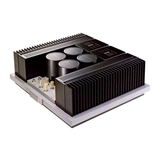
Table of Contents
Advertisement
CONTENTS
Features.......................................................... 2
Configuration of the Stereo System ................ 3
Connection Diagram ....................................... 4
Operation ....................................................... 5
Protective Circuitry ...................................... 5
Combinations with the M-25 ........................ 6
Maintenance ................................................... 6
Characteristics Charts ..................................... 7
Specifications ................................................. 8
IMPORTANT NOTICE
The serial number for this equipment is located on the
bottom plate. Please write this serial number on your
enclosed warranty card and keep in a secure area. This is
for your security.
WARNING: TO PREVENT FIRE OR SHOCK
HAZARD, DO NOT EXPOSE THIS
APPLIANCE TO RAIN OR MOISTURE.
Advertisement
Table of Contents

Summary of Contents for Pioneer M-25
-
Page 1: Table Of Contents
Features............2 Configuration of the Stereo System ....3 Connection Diagram ........4 Operation ............5 Protective Circuitry ........5 Combinations with the M-25 ......6 Maintenance ........... 6 Characteristics Charts ........7 Specifications ..........8 IMPORTANT NOTICE The serial number for this equipment is located on the bottom plate. -
Page 2: Features
Carefully Selected, High-quality Parts Class-AB circuitry. This feature guarantees an ultra wide Each and every part which makes up the M-25 has been frequency range which turns the attributes of the RET to singled out for its quality so that only the best is finally maximum advantage, and also a superior low-distortion chosen. -
Page 4: Connection Diagram
As shown in Fig. 1, connect the R (right) channel speaker to the M-25's R speaker output terminals, and the L (left) channel speaker to the M-25's L speaker output terminals. Both speakers are clearly marked with plus and minus polarities (red and white, respectively). -
Page 5: Operation
4 ohms). In such cases, the protective circuitry is automatically actuated, and the transistors and speakers are protected from any damage. Once the trouble is corrected, the protective circuitry will be automatically released, and the M-25 will return to its normal state of operation. -
Page 6: Combinations With The M-25
The M-25's name plate is designed so that it can be attached to face you, whichever direction the M-25 is pointing. All you have to do is to turn the M-25 upside down, and remove the screw fastening the name plate with a Phillips screwdriver. Then, attach the plate to that side which you want to face you. -
Page 8: Specifications
SPECIFICATIONS Miscellaneous Semiconductors Power Requirements ........ 120V, 60Hz only Transistors ..............55 Power Consumption ........320 watts (UL) Diodes................Dimensions......420(W) x 153(H) x 370(D)mm Amplifier Section 16-9/16 x 6 - 1 / 3 2 x 1 4-9/16 in. Circuitry . . . First stage current mirror loaded, Three-stage Weight without package .... - Page 10 Frequency Response: 5 to 20,000Hz +0dB, -1 .0dB Circuitry: First stage Current mirror Input Sensitivity/Impedance: 1V/50k ohms loaded, 3-stage Darlington Output parallel Push-pull pure Speaker: 4 ohms to 16 ohms complementary OCL (class AB Damping Factor: 60 (5 to 30,000Hz, 8 ohms) operation) Hum and Noise: 120dB...


Need help?
Do you have a question about the M-25 and is the answer not in the manual?
Questions and answers