Pioneer M-F10 Service Manual
Stereo power amplifier
Hide thumbs
Also See for M-F10:
- Operating instructions manual (40 pages) ,
- Service manual (28 pages) ,
- Operating instructions manual (146 pages)
Table of Contents
Advertisement
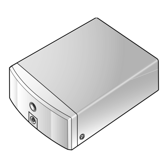
STEREO POWER AMPLIFIER
M-F10
THIS MANUAL IS APPLICABLE TO THE FOLLOWING MODEL(S) AND TYPE(S).
Model
Type
M-F10
MYXJ
NVXJ
KUXJ/CA
¶ This product is a system(s) component.
This product does not function properly independently ; to avoid malfunctions, be
sure to connect it to the prescribed system component(s), otherwise damage may
result.
¶ Please connect it to the STEREO CD TUNER XC-F10, for adjustment and operation
inspection.
Component
STEREO CD TUNER
STEREO POWER AMPLIFIER
SPEAKER SYSTEM
STEREO CASSETTE DECK
CONTENTS
1. SAFETY INFORMATION .................................... 2
2. EXPLODED VIEWS AND PARTS LIST ............. 3
......................................................... 8
4. PCB CONNECTION DIAGRAM ....................... 14
5. PCB PARTS LIST ............................................. 20
6. ADJUSTMENT .................................................. 23
PIONEER CORPORATION
PIONEER ELECTRONICS SERVICE, INC. P.O. Box 1760, Long Beach, CA 90801-1760, U.S.A.
PIONEER EUROPE NV Haven 1087, Keetberglaan 1, 9120 Melsele, Belgium
PIONEER ELECTRONICS ASIACENTRE PTE. LTD. 253 Alexandra Road, #04-01, Singapore 159936
PIONEER CORPORATION 2000
Power Requirement
AC220-230V
AC230V
AC120V
Model
XC-F10
M-F10
S-F10-LRW
CT-F10
4-1, Meguro 1-chome, Meguro-ku, Tokyo 153-8654, Japan
Service manual
RRV2319 (ZVYXJ type)
RRV2341 (ZUXJ/CA type)
RRV2321
RRV2330 (XMD/EW type)
RRV2346 (XMD/UC type)
RRV2308
7. GENERAL INFORMATION .............................. 24
7.1 DIAGNOSIS ................................................ 24
7.1.1 DISASSEMBLY ................................. 24
7.1.2 SINGLE OPERATION METHOD ...... 25
7.2 IC ................................................................ 27
.................................................................... 28
T-ZZA JUNE 2000 Printed in Japan
ORDER NO.
RRV2321
Remarks
Remarks
This manual.
Advertisement
Table of Contents

Related Manuals for Pioneer M-F10


Summary of Contents for Pioneer M-F10
-
Page 1: Table Of Contents
PIONEER CORPORATION 4-1, Meguro 1-chome, Meguro-ku, Tokyo 153-8654, Japan PIONEER ELECTRONICS SERVICE, INC. P.O. Box 1760, Long Beach, CA 90801-1760, U.S.A. PIONEER EUROPE NV Haven 1087, Keetberglaan 1, 9120 Melsele, Belgium PIONEER ELECTRONICS ASIACENTRE PTE. LTD. 253 Alexandra Road, #04-01, Singapore 159936 PIONEER CORPORATION 2000 T–ZZA JUNE 2000 Printed in Japan... -
Page 2: Safety Information
For the latest information, always consult the current Also test with plug reversed PIONEER Service Manual. A subscription to, or ad- (Using AC adapter ditional copies of, PIONEER Service Manual may be plug as required) obtained at a nominal charge from PIONEER. -
Page 3: Exploded Views And Parts List
M-F10 LITHIUM BATTERY NOTICE WARNING! ADVARSEL! Lithiumbatteri − Eksplosionsfare ved Lithium batteries. Danger of explo- sion. Replacement must be done by fejlagtig håndtering. Udskiftning må kun qualified personnel and only by fol- ske med batteri af samme fabrikat og lowing the instructions given in the type. - Page 4 M-F10 (1) PACKING PARTS LIST Mark No. Description Part No. Mark No. Description Part No. Paper Pattern AAX7807 Lithium Battery (CR2025) VEM1009 Vinyl Bag (115 × 270 × 0.05) System Cable (20P) ADE7057 Z21–013 AC Power Cord See Contrast table (2) Polyethylene Bag Z21–038...
- Page 5 M-F10 Note: when you order the bonnet (No.27), 2.2 EXTERIOR please order Caution Label (No.29) too and paste it to the bonnet. KUXJ/CA Only KUXJ/CA Only KUXJ/CA Only Refer to "2.3 HEAT SINK ASSY". KUXJ/CA Only KUXJ/CA Only Holder Unit...
- Page 6 M-F10 (1) EXTERIOR SECTION PARTS LIST Mark No. Description Part No. Mark No. Description Part No. AC IN Assy See Contrast table (2) LED Lens PNW2019 PRIMARY Assy See Contrast table (2) Bonnet AZN7837 SECONDRY Assy See Contrast table (2)
- Page 7 M-F10 2.3 HEAT SINK ASSY (1) HEAT SINK ASSY SECTION PARTS LIST Mark No. Description Part No. Mark No. Description Part No. AMP Assy AWU7560 Screw BBZ30P160FMC REG Assy AWU7561 Screw BPZ30P350FZK DC Fan Motor AXM7014 Power Pac Holder ANG7109...
-
Page 8: Block Diagram And Schematic Diagram
M-F10 3. BLOCK DIAGRAM AND SCHEMATIC DIAGRAM Note: When ordering service parts, be sure to refer to "EXPLODED VIEWS AND PARTS LIST" or "PCB PARTS LIST". 3.1 BLOCK DIAGRAM and OVERALL CONNECTION DIAGRAM : AUDIO SIGNAL ROUTE PRIMARY ASSY (AWU7557: MYXJ, NVXJ types) - Page 9 M-F10 IC31 REG ASSY (AWU7561: MYXJ, NVXJ types) (AWU7619: KUXJ/CA type) The power supply is shown with the marked box. AKE1025 (MYXJ, NVXJ) AKE7065 (KUXJ/CA) BALANCED BUFFER IC3021 (HP) (HP)
- Page 10 M-F10 3.2 AC IN, PRIMARY and SECONDRY ASSYS SECONDRY ASSY (AWU7558: MYXJ, NVXJ types) CAUTION : FOR CONTINUED PROTECTION AGAINST RISK OF FIRE. (AWU7614: KUXJ/CA type) REPLACE WITH SAME TYPE NO. 491010 MFD. BY LITTELFUSE INC. FOR IC11 and IC12 (AEK7022).
- Page 11 M-F10 3.3 REG, HP and LED ASSYS REG ASSY (AWU7561: MYXJ, NVXJ types) (AWU7619: KUXJ/CA type) +18V –18V CN52 +21V CN51 CN3953 (HP) (HP) LED ASSY (AWU7562) (HP) 270: MYXJ, NVXJ (MYXJ, NVXJ) 1k: KUXJ/CA V+12 (KUXJ/CA) CN5601 J3953 (MYXJ, NVXJ)
- Page 12 M-F10 3.4 AMP and COMPLEX ASSYS SIGNAL ROUTE : AUDIO SIGNAL : AUDIO SIGNAL (CENTER) (HP) : AUDIO SIGNAL (HEADPHONE) BALANCED BUFFER 8.8V CN3012 –8.8V (HP) (HP) (HP) –8.8V 8.8V MYXJ, NVXJ Only (HP) –28V –28V CN5802 J3953 (HP) V+12...
- Page 13 M-F10 CN51 CAUTION : FOR CONTINUED PROTECTION AGAINST RISK OF FIRE. REPLACE WITH SAME TYPE NO. 491005 MFD. BY LITTELFUSE INC. FOR IC53 (AEK7019). CN11 The power supply is shown KUXJ/CA with the marked box. Only 491005 D3001 (AKE7019) 1SS133-T: MYXJ, NVXJ...
-
Page 14: Pcb Connection Diagram
M-F10 4. PCB CONNECTION DIAGRAM NOTE FOR PCB DIAGRAMS: Symbol in PCB Symbol in Schematic Part Name 1. Part numbers in PCB diagrams match those in the schematic Diagrams Diagrams diagrams. 2. A comparison between the main parts of PCB and schematic diagrams is shown below. - Page 15 M-F10 SIDE B SECONDRY ASSY PRIMARY ASSY (ANP7345–C) (ANP7345–C) AC IN ASSY (ANP7345–C)
- Page 16 M-F10 4.2 COMPLEX, AMP, REG, HP and LED ASSYS SIDE A COMPLEX ASSY REG ASSY IC31 IC53 IC54 (ANP7345–C) Front (ANP7345–C)
- Page 17 M-F10 SIDE A AMP ASSY IC3401 IC3301 To FAN MOTOR IC3411 LED ASSY (ANP7345–C) HP ASSY (ANP7345–C) (ANP7345–C)
- Page 18 M-F10 SIDE B COMPLEX ASSY AMP ASSY Q3471 Q3474 Q3402 Q5803 Q3312 Q5804 Q3401 IC5801 IC3401 Q3659 Q5802 Q3311 Q3313 IC3451 IC3901 Front IC3021 Q3023 Q3024 LED ASSY IC3001 HP ASSY (ANP7345–C) Q3953 Q3951 Q3952 (ANP7345–C) (ANP7345–C)
- Page 19 M-F10 SIDE B Q3603 REG ASSY Q3602 Q3604 Q3607 IC51 Q3654 Q3651 Q3652 Q3653 Q5601 (ANP7345–C) Front (ANP7345–C)
-
Page 20: Pcb Parts List
M-F10 5. PCB PARTS LIST NOTES : ÷ Parts marked by “ NSP ” are generally unavailable because they are not in our Master Spare Parts List. ÷ The mark found on some component parts indicates the importance of the safety factor of the part. -
Page 21: Primary Assy
M-F10 AMP Assy AWU7560 and AWU7618 are constructed the same except for the following: Part No. Symbol and Description Remarks Mark AWU7560 AWU7618 ∗ L3021 LAU560J Not used ∗ : As for the AWU7560, the design change is done like the AWU7618. - Page 22 M-F10 Mark No. Description Part No. Mark No. Description Part No. R5808 RD1/4PU223J OTHERS R3699 RD1/4PU330J 8P CABLE HOLDER 51052–0800 R5823 RD1/4PU472J JUMPER WIRE D25XYY0815E Other Resistors RS1/10S OTHERS COMPLEX ASSY CN3082 2P CONNECTOR 5569–02A1 3081 SPEAKER TERMINAL 4-P AKE1025...
-
Page 23: Adjustment
M-F10 Mark No. Description Part No. Mark No. Description Part No. C3412, C3413 CKSQYB473K50 LED ASSY C3031, C3032 CKSQYB474K16 C3023, C3911, C3912 CKSQYF104Z25 SEMICONDUCTORS C3026, C3901, C3902 CKSQYF105Z16 D5601 SLR–343VC C3408, C3409 CKSQYF473Z50 RESISTORS C3453 CQMBA683J50 All Resistors RS1/10S RESISTORS... -
Page 24: General Information
M-F10 7. GENERAL INFOMATION 7.1 DIAGNOSIS 7.1.1 DISASSEMBLY 20–30 degrees apporox. Disconnect the CN3953 Remove the Front Panel. Remove the Bonnet Case. COMPLEX Assy Remove the Rear panel. -
Page 25: Single Operation Method
M-F10 7.1.2 SINGLE OPERATION METHOD Voltage of each part and method of diagnosing each IC Test Point for Service FOR SERVICE COMPLEX ASSY COMPLEX ASSY 1. AC RY SIDE B FOR SERVICE 3. MUTE FOR SERVICE 2. SP RY Diagnosis of Voltage of Each Part FOR SERVICE 1. - Page 26 M-F10 Diagnosis Points For IC3001 confirmation R– For IC3901 confirmation GNDA For IC3301 confirmation L– For IC3451 confirmation For IC3401 confirmation ROUT LOUT COMPLEX ASSY FRONT AMP ASSY R IN SIDE B C IN L IN SIDE B GNDA GNDA...
- Page 27 M-F10 ¶ The information shown in the list is basic information and may not correspond exactly to that shown in the schematic diagrams. 7.2 IC M62421FP (IC3021: AMP ASSY) Digital Sound Controller built-in Tone Control Pin Assignment (Top View) Block Diagram Pin Function No.
-
Page 28: Panel Facilities And Specifications
M-F10 8. PANEL FACILITIES AND SPECIFICATIONS 8.1 PANEL FACILITIES For KUXJ/CA Type 1 Power indicator – lights when the system is on Output for Satellite Speakers 2 Headphone jack – plug in a pair of headphones for private Continuous average power output of 20 watts* listening (the sound from the speakers is muted when head- per channel, min., at 8 ohms, from 200 Hz to...
Need help?
Do you have a question about the M-F10 and is the answer not in the manual?
Questions and answers