
Related Manuals for Star Headlight & Lantern LCS790


Summary of Contents for Star Headlight & Lantern LCS790
- Page 1 INSTALLATION AND OPERATING INSTRUCTION MANUAL LCS790 LCS790 LCS790 LCS790 SIREN AMPLIFIER & LIGHT CONTROLLER US PATENT D574,799 PLIT411 REV. - 9/23/08...
-
Page 2: Purchase Date
Installation Information LCS790 MODEL: AMPLIFIER SERIAL NO: CONTROL HEAD SERIAL NO: ARROWSTICK CONTROL SERIAL NO: Model and serial number located on bottom of unit INSTALLATION INFORMATION PURCHASE DATE: INSTALLATION DATE: INSTALLER: DEALER:... -
Page 3: Table Of Contents
Table of Contents TABLE OF CONTENTS OVERVIEW PRECAUTIONS CONTENTS SPECIFICATIONS INSTALLATION 4-40 INSTALLER-SELECTABLE OPTIONS 4-31 DIP Switch Settings DIP Switch Chart BUZ (Beep Settings), GUN (Gun Lock), TDM (Traffic Director Mode) PD (Pursuit Disable), AUX (Auxiliary Input), PGM (Programming Mode) PK (Park-Kill Polarity), AUX (Auxiliary Input Polarity) Programmable Settings 9-31... -
Page 4: Overview
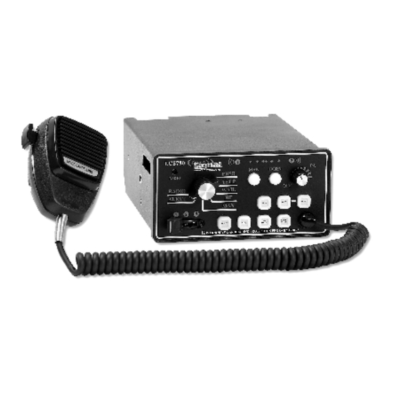
Overview LCS790 Overview The LCS790 Siren Amplifier is a premium 200W unit designed for single or dual 100W speaker use and full lighting control. The primary operating modes are Phaser, Yelp, Wail, Hands Free, Manual, Alert, and Radio. A Noise Canceling PA Override and push-button Horn Override are available in all modes. -
Page 5: Precautions
Installation Information Precautions Proper installation of the unit is essential for years of safe, reliable operation. Please read all instruction before installing the unit. Failure to follow these instructions can cause serious damage to the unit or vehicle and may void warranties. -
Page 6: Specifications
Specifications Specifications Input Voltage 10 - 16 VDC (negative ground) Input Current 8.0 Amps @ 13.6 VDC (single 100W speaker) 16.0 Amps @ 13.6 VDC (dual 100W speakers) Standby Current 0 mA while Off, <150 mA with backlighting on Max Peak Current 50 AMPS (supply circuit must be capable of supplying this for brief period) Audio Frequency 200Hz - 10 kHz + 3db... -
Page 7: Installation
Optional Settings The LCS790 has quite a few different options that can be modified to meet your particular needs. Please review BOTH the list below and the one on page 10 to determine if you need to change any of the settings for your application. - Page 8 Installation: Dip Switch Settings (cont’d) UPSIDE DOWN VIEW There are two sets of DIP switches located inside the unit. One set has six switches that move up or down. The default position for all of these switches is “down” (closer to the circuit board). The other set contains two DIP switches that slide in or out.
- Page 9 Installation: Dip Switch Settings (cont’d) UP/DOWN DIP SWITCHES DOWN POSITION LABEL FUNCTION UP POSITION (Default) Keypad buttons beep Keypad buttons silent when pressed and when pressed and Beep Setting 10-second beep option No 10-sec beep option also available available. Switch 4 used to Switch 4 is a normal On/ Gun Lock unlock the Gun Lock...
- Page 10 Installation: Dip Switch Settings (cont’d) UP/DOWN DIP Switch Settings Beep Settings By default, every time a button is pressed on the keypad, the unit beeps. Flip the DIP switch up to deactivate this feature. Please note: The optional 10-second beep function will not work if this switch is in the UP position (see page 15 of the Detailed Programming section for further details).
- Page 11 Installation: Dip Switch Settings (cont’d) Pursuit Disable The farthest right slide switch position is normally used for “pursuit mode”. By default, when the slide switch is in position the lights connected to it will activate, the siren will activate in Wail mode, and your compatible traffic director (if connected to this unit) will activate in the Warn...
- Page 12 Installation: Dip Switch Settings (cont’d) Detailed Programming IN/OUT DIP Switch Settings There are an additional two DIP switches located to the right of the bank of six. These switches move in and out, rather than up and down (like the previous switches).
-
Page 13: Detailed Programming Summary Table
Installation: Detailed Programming Detailed Programming Summary Table Detailed Programming Summary Table The options below should be programmed PRIOR to installation of your siren. Refer to pages 12-31 for detailed programming instructions. Option Default Setting Optional Setting Activating a Button (Turning it Button Operation Activating Button (Turning it on) Opens on) Will Close The Circuit... -
Page 14: Detailed Programming Legend
Installation: Detailed Programming Detailed Programming Legend Detailed Programming Legend ROTARY PUSH KNOB FUNCTION DEFINITION BUTTON POSITION Default PHASER Gun Lock Buttons ONLY S4 YELP Button Operation (Open or Closed) ALL OPEN WAIL Button Operation (Momentary or Latched) ALL LATCHED Button State at Power Up ALL OFF Steady or Flashing/Pulsed Outputs ALL STEADY... -
Page 15: Detailed Programming Instructions (See Page 10 For Specific Page Numbers For Each Option)
Installation: Detailed Programming Button Operation (Open or Closed) Detailed Programming Instructions The following section gives a detailed description of how to program each of the options listed/shown on the previous two pages. If you do not need to change any of these options, you may skip to the Mounting section on page 32. - Page 16 PGM DIP switch down to save the changes. Push Button State At Power Up Each button, by default, operates as a standard switch. When the LCS790 unit is powered up, they are all in the OFF mode. Pressing each button once will turn it ON and pressing it again will turn it OFF.
- Page 17 Installation: Detailed Programming Gun Lock Button Options Please Note: You must have the Gun Lock DIP switch (GUN) on to use these two features (see page 7). Optional Gun Lock Button All of the buttons, by default, operate as standard push button switches. Pressing each button once will turn it ON and pressing it again will turn it OFF.
- Page 18 Installation: Detailed Programming Auto Beep Function Please Note: You must have the Beep DIP switch (BUZ) on to use this feature (see page 7). Auto Beep When Any Function Active This unit can be programmed to “Beep” every 10 seconds whenever any functions are activated.
- Page 19 Installation: Detailed Programming Steady or Pulsed Output Options Steady or Flashing/Pulsed Outputs The outputs switched by each push button normally apply steady +12 VDC. If you would like any of these outputs to be flashing or pulsed (i.e. if you were hooking it up to a light that didn’t have its own flasher), change this setting.
- Page 20 Installation: Detailed Programming MAN Step Up and HF Sweep Options Manual “Step-Up” Function Time Out By default, when a siren tone is activated, pressing the Manual button will advance it (or “step it up”) to the next siren tone, where it will remain until you deactivate or change it.
- Page 21 Installation: Detailed Programming Siren Disable and Audio Lockout Siren Disable (PA and Horn Functions only) If you desire to COMPLETELY disable the siren feature from this unit, allowing only the PA, Horn, and Radio audio functions (applications such as security, volunteer, training etc.), change this setting.
-
Page 22: Standby Mode
Installation: Detailed Programming Standby Mode Standby Mode (Stealth Mode) By default, all of the functions on this unit can be activated at any time. If you would like the unit to remain in “Standby” mode (all features and faceplate lighting disabled) until the slide switch is activated, change this setting. - Page 23 Installation: Detailed Programming Slide Switch Auto-Activation of Warn Pattern Slide Switch Activates Warn Pattern (on Traffic Director) Under normal operation, when you place the siren in “Pursuit” mode by moving the slide switch to Position , the Traffic Director will automatically activate and display the Warn pattern.
- Page 24 Installation: Detailed Programming Basic Slide Switch Auto-Activation of Siren Basic Slide Switch Auto-Activation of Siren Under normal operation, when you place the siren in “Pursuit” mode by moving the slide switch to Position 3 3 3 3 , the Siren will automatically activate with the WAIL tone.
- Page 25 Installation: Detailed Programming Advanced Siren Auto-Activation Advanced Siren Auto-Activation (Slide Switch and/or Push Buttons) As indicated on the previous page, by default, when you place the unit in “Pursuit” mode by moving the slide switch to Position 3 3 3 3 , the siren will automatically activate with the WAIL tone.
- Page 26 Installation: Detailed Programming Tone Change Lockout and Push Button Auto-Activation Tone Change Allowed While In Audible Pursuit The default programming for this siren allows you to move the rotary knob and change the tone at any time. If you would like to prevent the tone from being changed while you are in pursuit mode, change this setting.
-
Page 28: Quick Installation Guide
QUICK INSTALLATION GUIDE REMOVABLE CENTERFOLD QUICK INSTALLATION CHECKLIST • 8 AWG Wire to Ground Terminal • +12VDC to three Light Power Terminals (Use 8 AWG) • Lights connected to S1-S7 outputs • +12VDC for Backlighting to Terminal 2 of 10-way conn. •... - Page 29 S30042-135 Please note that the screws should be located on the bottom of this connector, as it plugs into the back of the unit. Please note that the screws should be located on the top of this connector, as it plugs into the back of the unit. S30041-68 WARNING LIGHT OUTPUTS POWER FOR LIGHTS...
- Page 31 Installation: Detailed Programming Push Button Auto-Activation (CONT’D) Slide Switch Auto Activation of Push Button Functions (CONT’D S1-S7 are Red: Functions tied to each Red button (S1-S7) WILL automatically activate whenever the slide switch is moved to Position 1 1 1 1 . HORN is Red: Function tied to SS2 output WILL automatically activate whenever the slide switch is moved to Position 1 1 1 1 .
- Page 32 Installation: Detailed Programming Rotary Tones Auto-Activate Slide Switch Functions Rotary Switch Tones Auto-Activate Slide Switch Functions This unit allows you to program the slide switch functions to automatically activate when the rotary switch is placed in the WAIL, YELP, or PHSR positions.
- Page 33 Installation: Detailed Programming Park-Kill De-activation of Lights Park-Kill De-activation of Functions The Park-Kill option will automatically shut off the siren when activated by an external switch (i.e. the vehicle is put in park, a door is opened, etc.). By default, the Park-Kill option for this unit (described on page 37) only disables the siren.
- Page 34 Installation: Detailed Programming Phaser Tone Override/Disable High-Low (Two-Tone) Override of Phaser Tone By default, the Phaser tone is enabled on this siren. This tone can be replaced with a High/Low siren (also known as Two Tone or the European sound). This feature would be used in areas where the High/Low tone was desired instead of the Phaser sound.
- Page 35 Installation: Optional Settings Horn Ring Transfer (HRT) Options HRT Active Mode By default, if you connect the Horn Ring Transfer (HRT) option (see Horn Out and Auxiliary wires in wiring diagram on page 39), you can control the siren any time it is on (see page 38). If you would like this feature to be disabled until the slide switch or certain buttons are activated, change this setting.
- Page 36 If you will be connecting a Traffic Director to this unit, be sure that you have set the TDM jumper for Traffic Director Mode (as explained on page 7). The LCS790 can be programmed for compatibility with a number of different traffic directors. The default settings of this unit allow for operation of a traffic director controlled by our TDC850 (i.e.
- Page 37 There may be rare occasions where you may wish to disable the COM port (telephone style jack) on the back of the LCS790. Or there may be some applications that require the use of a Traffic Director that is wired differently than the DL15-30W.
- Page 38 Installation: Optional Settings Reset to Factory Defaults Reset To Factory Defaults If at anytime during the programming, you are unsure of what settings you have changed, you can reset the unit back to the factory defaults. To reset the siren to its factory default settings, perform the following. Place the PGM DIP switch in this position: Place the Rotary Knob in this position: Radio...
-
Page 39: Mounting
(OSHA 1910.95) • The LCS790 siren may be mounted above the dash, below the dash, or in a rack with the mounting u-bracket provided. • Choose a mounting location convenient to the operator and away from any air bag deployment areas. -
Page 40: Electrical Connections
Installation Electrical Connections Electrical Connections Electrical connections to the unit are made using several terminals and re- movable connectors located on the back of the unit. The unit is protected by a 20 amp fuse on the input power and each output is protected by a 20 amp fuse. - Page 41 Installation Wiring Connections Wiring Connections Power (+12VDC) and ground connections are made through several terminal blocks on the back of the siren. Ground: Make your ground connection using an 8 AWG wire. Connect it to the single terminal located on the left side of the rear of the siren.
-
Page 42: 12-Terminal Connector
Installation: Wiring 12-Terminal Connector i t . Current (Amps) The chart to the right shows the 18 AWG 18 AWG 18 AWG required wire gauge to be used 18 AWG 16 AWG 16 AWG for each output (1-12) above, 18 AWG 16 AWG 14 AWG based upon the current draw of... - Page 43 Installation Wiring Diagram #1 S1-S4 Lights Slide Switch Lights Video Traffic Director -36-...
-
Page 44: 10-Terminal Connector
Installation: Wiring 10-Terminal Connector Park/Kill: (Terminal 1) - Used for the Park/Kill feature that automatically deactivates the siren (such as when the vehicle is placed in Park or a door is opened). Using an 18 AWG wire, connect this terminal to the dome light, a door switch, or other external switch. -
Page 45: Terminal Connector
Installation: Wiring 10-Terminal Connector (CONT’D) Auxiliary: (Terminal 5) - Used for remote Manual (or Air Horn) control. Using an 18 AWG wire, connect to the horn ring circuit or some other remote switch. Typically the Horn wire is disconnected from the Horn and connected to this wire. - Page 46 Installation Wiring Diagram #2 Top Of Siren Bottom Of Siren -39-...
-
Page 47: Label Insertion
Label Insertion LABEL INSERTION Once the wire connections have been made to S1-S7, labels can be inserted into the switches. The product is shipped with 49 different labels for these push buttons. Select the desired label inserts. Insert the label into each button and tuck it under the lip of the switch. -
Page 48: Operation
Operation On/Off Operation General This unit is designed for easy operation under the stress associated with high-speed pursuit. Most siren functions and/or light controls are accessible with one simple motion without repetitive activation of switches or automatic timed switching that can interfere with desired operation. On/Off The On/Off-PA volume control (PA) will both turn the siren unit on and off, as well as control the public ad-... -
Page 49: Selector Switch (Rotary Knob)
Operation Rotary Knob Selector Switch (Rotary Knob) Whenever you turn the unit on by rotating the PA button clockwise, the rotary selector switch will control the primary operating function of the siren. PHSR - (Phaser) Ultra-fast changing tone used for maximum attention. YELP - A rapidly changing tone used in congested areas. -
Page 50: Slide Switch
Operation Slide Switch and Push Buttons Slide Switch The slide switch is designed for quick pursuit mode operation. The far left position (OFF) will not activate any outputs. Using the default settings, Position will activate any lights or devices connected to Terminals 1 and 2 of the 12-terminal connector (see pages 35-36). - Page 51 Manual and Air Horn MAN and HORN Buttons The front panel of the LCS790 contains two pushbuttons that operate the Manual function and the Air Horn. MAN – When the selector switch is in the WAIL, YELP or PHSR positions, pressing the MAN button cycles through to a quicker changing tone (see table below).
-
Page 52: Volume Controls
Rotating it clockwise will power up the LCS790. As it is turned clockwise, the outside volume of the PA will increase. -
Page 53: Auxiliary Input
Operation: Auxiliary Input and Park-Kill Fuses and Parts Auxiliary Input During installation an auxiliary input may be connected to the vehicle horn ring or other switching device. It provides the same operation as pressing the HORN button or optionally the MAN button. (See the Installation: Wiring section on page 38 for details.) Park Kill (Cutout) During installation, the Park Kill input may be connected to a door switch. -
Page 54: Service
Service and Troubleshooting Service This unit is designed to provide years of reliable service under even the worst conditions. Many times there may appear to be a problem with the unit when the true problem is in the speaker(s) or improper installation. The following chart shows typical symptoms and possible causes. -
Page 55: Warranty
Warranty and Return LIMITED WARRANTY Signal Vehicle Products warrants this new product to be free from de- fects in material and workmanship, under normal use and service, for a period of one (1) year from the date of delivery to the first user-purchaser. During this warranty period the obligation of Signal Vehicle Products is limited to repairing or replacing, as Signal Vehicle Products may elect, any part or parts of such product which after examination by Signal Vehi-... -
Page 56: Returned Goods Authorization Form
RGA number (Returned Goods Authorization Number). No returns will be al- lowed for product returns that are not listed on the RGA. Please fill out the form below and enclose it with the returned product(s). Returned Goods Authorization Form LCS790 MODEL: Serial Number...
Need help?
Do you have a question about the LCS790 and is the answer not in the manual?
Questions and answers