Table of Contents
Advertisement
Quick Links
LCS771
LCS771
LCS771
LCS771
(Also applies to LCS771- - - - 28)
(Also applies to LCS771
(Also applies to LCS771
(Also applies to LCS771
Installation and Operating Instructions
Installation and Operating Instructions
Installation and Operating Instructions
Installation and Operating Instructions
SIREN
SIREN
SIREN
SIREN
28)
28)
28)
PLIT553 REV B
6/18/21
Advertisement
Table of Contents

Related Manuals for Star Headlight & Lantern STARSIGNAL LCS771


Summary of Contents for Star Headlight & Lantern STARSIGNAL LCS771
- Page 1 LCS771 LCS771 LCS771 LCS771 SIREN SIREN SIREN SIREN (Also applies to LCS771 (Also applies to LCS771- - - - 28) (Also applies to LCS771 (Also applies to LCS771 Installation and Operating Instructions Installation and Operating Instructions Installation and Operating Instructions Installation and Operating Instructions PLIT553 REV B 6/18/21...
-
Page 2: Table Of Contents
Installation Information MODEL: LCS771 or LCS771-28 or LCS771-LM Serial #: PURCHASE DATE: INSTALLATION DATE: INSTALLER: DEALER: Model and serial number located on bottom of unit TABLE OF CONTENTS GENERAL DESCRIPTION INSTALLATION NOTES MOUNTING TIPS ELECTRICAL CONNECTIONS Wiring Diagram Wiring Size and Termination Mandatory Connections Optional Connections INSTALLER SELECTABLE OPTIONS... -
Page 3: General Description
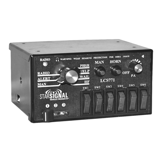
General Description The LCS771 Siren Amplifier is a premium 200W unit designed for dual 100W speaker use. It can be utilized with or without an optional hand held microphone (not included with the LCS771-LM). The primary operating modes are Phaser, Yelp, Wail, Hands Free, Manual, Alert, and Radio. -
Page 4: Electrical Connections
Electrical Connections Electrical connections to this unit are made at several locations on the back of the siren: Most siren related connections are made through the removable green 12-terminal connector located in the rear of the unit (See below - Part # CPSS-153). -
Page 5: Wiring Size And Termination
(Electrical Connections CONT’D) Wire Size and Termination Examine the charts below to determine the proper gauge of the wire to use. Please review the following recommendations when making your electrical connections: For safety and reliability we highly recommend that you always use both Ground terminals (3 &... -
Page 6: Mandatory Connections
(Electrical Connections CONT’D) Mandatory Electrical Connections Ground - Connect terminals 3 & 4 of the green connector to the negative terminal of the battery. (You MUST connect both of these terminals!!) Siren Power - Connect Terminals 1 & 2 of the green connector to a 10- 16VDC ignition switched power source (19-30VDC for the LCS771-28). - Page 7 (Optional Electrical Connections CONT’D) Backlighting - Connect terminal 11 of the green connector to the dash lights, ignition switched power, or other switched 10- 16VDC (19-30VDC for the LCS771-28) power source. This controls the backlighting for the face of the siren. Park/Kill Feature - If you would like the siren to automatically disengage when the vehicle door is opened or when the vehicle is placed into park, connect terminal 12 of the green connector to the dome light,...
-
Page 8: Installer Selectable Options
Installer Selectable Options DIP Switch Settings: There are two banks of DIP switches that control various options on this siren, a bank of 7 switches and a bank of 2 switches. 7 DIP Switch Bank While facing the siren, on the left side of the box you will find an opening that allows you access to 7 DIP switches. -
Page 9: Optional Tone Programming
(Installer Selectable Options CONT’D) Optional Tone Programming The LCS771 will produce 7 different tones/sounds by activating its various functions: Function Default Tone Phaser Step Up Two-Tone (PHSR+MAN) PHSR Phaser YELP Yelp WAIL Wail Ramp Up HORN Air Horn Air Horn Proceed below if you wish to reprogram any of these functions for a different tone. -
Page 10: Additional Options
(Installer Selectable Options CONT’D) Wind Down or Hard Stop Option † By default, the Wail tones indicated by the “†” in the Optional Tone list on the previous page will “wind down” when they are de-activated. If you prefer to have them immediately stop (i.e. -
Page 11: Operation
Operation General This unit is designed for easy operation under the stress associated with high-speed pursuit. Most siren functions are accessible with one simple motion without repetitive activation of switches or automatic timed switching that can interfere with desired operation. Power/PA Knob The PA knob is located in the upper right hand corner of the front face. -
Page 12: Man Button
(Operation CONT’D) The front panel of the LCS771 contains two momentary push-button switches for the Manual function and the Air Horn. MAN Button Rotary Switch Position Function When MAN Pressed MAN or HF Produces a rising siren tone while being pressed. The siren output “winds down”... -
Page 13: Rocker Switches
(Operation CONT’D) Rocker Switches 6 lighted rocker switches control the devices connected to the corresponding colored wires described on pages 2-5. Radio Volume The radio repeat volume (Radio) control is recessed in the upper left hand corner of the front face. This should be set when the vehicle is parked. -
Page 14: Troubleshooting
Troubleshooting This unit is designed to provide years of reliable service under even the worst conditions. Many times there may appear to be a problem with the unit when the true problem is in the speaker(s) or improper installation. The following chart shows typical symptoms and possible causes. -
Page 15: Specifications
Fuse This audio and logic circuitry in this unit is protected by a 20A automotive type fuse located on the back of the siren. If it blows, be sure to identify the cause of the blown fuse prior to replacing it. Please note: There should also be separate user supplied fuses on all of your power input wires. -
Page 16: Warranty
ONE YEAR LIMITED WARRANTY The manufacturer warrants each new product against factory defects in material and workmanship for one year after the date of purchase. The owner will be responsible for returning to the Service Center any defective item(s) with the transportation costs prepaid.
Need help?
Do you have a question about the STARSIGNAL LCS771 and is the answer not in the manual?
Questions and answers