Table of Contents
Advertisement
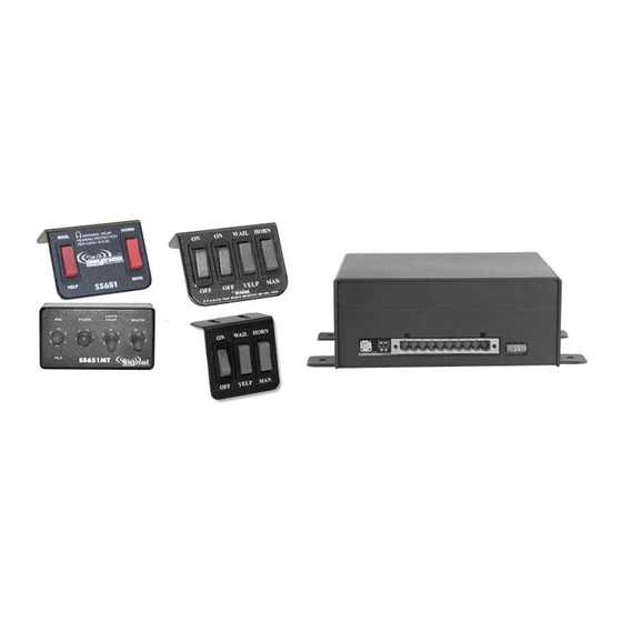
SS651- - - - 013, SS651MT
SS651
SS651
SS651
LCS653- - - - 013, and LCS653
LCS653
LCS653
LCS653
013, and LCS653
013, and LCS653- - - - 1 1 1 1 - - - - 013
013, and LCS653
Contents
Amplifier box
Wiring Connector
Control head (switch panel)
Blue ¼" quick connect terminals
Pink ¼" quick connect terminals
Input Voltage
Audio Input Current
Standby Current
Output Power
Siren Frequency
High Voltage Protection
Short Circuit Current
Operating Temperature
Size
Boxed Weight
013, SS651MT- - - - 013
013, SS651MT
013, SS651MT
Siren Amplifiers
Siren Amplifiers
Siren Amplifiers
Siren Amplifiers
SS651
LCS653
1
1
1
1
1
1
0
6
6
6
10 - 16 VDC (negative ground)
8 Amps @ 13.6 VDC (100W speaker)
Enable wire off 0mA
Backlighting off: 8 mA
105 WATTS RMS MAX. (15.0 VDC - single 100W speaker)
675Hz - 5kHz
> 16 VDC will cause siren output to cease, resume at normal
< 10 VDC will cause siren output to cease, resume at normal
50 AMPS (supply circuit must be capable of supplying this)
-15° F to +140°F
Amplifier: 2" High, 6" Wide, 5-3/4" Deep
(plus 3/4" flange on each side)
SS651-CH / SSS651-CH4 Control Head (Switch Panel):
3" High x 3" Wide, x 1-1/2" Deep
SS651-CH3 Control Head (Switch Panel)
3" High x 2-3/8" Wide, x 1-1/2" Deep
SS651MT-CH - Weatherproof Control Head:
2.5" High x 4.5" Wide x 2-1/8" Deep (3" Deep
with switches)
SS651, LCS653, and LCS653-1 - 3.4 lbs.
SS651MT - 4.3 lbs.
013
013
013
013
013
013
LCS653-1
SS651MT
1
1
1
1
1
1
3
0
6
0
PLITSTR248 REV. J
1/14/15
Advertisement
Table of Contents

Related Manuals for Star Headlight & Lantern SS651-013


Summary of Contents for Star Headlight & Lantern SS651-013
- Page 1 SS651- - - - 013, SS651MT SS651 013, SS651MT- - - - 013 SS651 SS651 013, SS651MT 013, SS651MT LCS653 LCS653 LCS653 LCS653- - - - 013, and LCS653 013, and LCS653 013, and LCS653- - - - 1 1 1 1 - - - - 013 013, and LCS653 Siren Amplifiers Siren Amplifiers...
-
Page 2: Table Of Contents
INSTALLATION NOTES MOUNTING ELECTRICAL CONNECTIONS WIRING DIAGRAMS DIP SWITCH SETTINGS OPTIONAL TONE PROGRAMMING OPERATION TROUBLESHOOTING WARRANTY/SERVICE Installation Information MODELS: SS651-013 SS651MT-013 LCS653 LCS653-1 SERIAL NO: DIP SWITCH OPTIONS PURCHASE DATE: _____ Negative Aux. Polarity DEALER: _____ Hands Free Enabled INSTALLATION DATE:... -
Page 3: Installation Notes
Installation Notes Proper installation of the unit is essential for years of safe, reliable operation. Please read all instructions before installing the unit. Failure to follow these instructions can cause serious damage to the unit or vehicle and may void warranties. Qualifications The installer must have a firm knowledge of basic electricity, vehicle electrical systems and emergency equipment. - Page 4 (Mounting CONT’D) MOTORCYCLE/MARINE AMP INSTALLATIONS (SS651MT ONLY!) This SS651-AMP can be used on a motorcycle or for marine applications by sealing the case with silicone sealant along the mating edges and around the wire connector. In order to reduce water entry, the amplifier should be oriented with the wire connector faced down.
-
Page 5: Electrical Connections
Electrical Connections Wire Size and Termination Electrical connections to this unit are made through the green 10-terminal connector located in the rear of the unit (P/N P30041-177). Examine the charts below to determine the proper gauge of the wire you should use. -
Page 6: Wiring Diagrams
(Electrical Connections CONT’D) Program Button Micro Feedback LED DIP Switches 10-Terminal Connector SWITCH PANEL +12 VDC Positive Side Horn Switch SPEAKER 11 OHMS VEHICLE HORN Positive AUX Horn Jumper +12 VDC Negative Side Horn Switch VEHICLE HORN Negative AUX Horn Jumper BATTERY MANDATORY ELECTRICAL CONNECTIONS Ground - Connect terminal 5 to the negative terminal of the battery. - Page 7 (Electrical Connections CONT’D) CONNECTION OF CONTROL HEADS SS651-CH (for SS651), SS651-CH3 (for LCS653-1), and SS651-CH4 (for LCS653) SS651-CH Please note that pressing the switch up activates the bottom terminal and pressing the switch down activates the top terminal. Wail Manual Good Good Chassis...
-
Page 8: Dip Switch Settings
DIP Switch Settings These sirens have two optional settings that can be selected during installation using the DIP switches located on the back of the amplifier case: • Auxiliary Input Polarity • Hands Free Cycler Mode Enable DIP Switches UP (Off) FUNCTION DOWN (On) SWITCH... -
Page 9: Optional Tone Programming
Optional Tone Programming These sirens can be programmed to produce 6 different tones/sounds by activating its various functions: Function Default Tone Wail Wail Yelp Yelp Yelp Step Up Phaser Manual Ramp Up Horn Air Horn Auxiliary Air Horn Each Function listed above can be programmed for a different tone. If you would like to change the tone for any of the six functions, follow the instructions below. -
Page 10: Operation
Operation Wail/Off/Yelp Button This is the 3-position button used for basic operation of the siren. While in the Wail or Yelp positions the siren will produce the tone programmed for that function (see previous page). The Wail and Yelp functions are defaulted for the Wail and Yelp tones. -
Page 11: Troubleshooting
Troubleshooting Auto Shutdown This unit is designed to automatically shut down when certain undesirable conditions exist, to prevent internal damage. All audio functions are disabled until the issue is corrected. • Over Voltage/Under Voltage • Over Current Micro Feedback LED This unit is designed with an LED that not only provides feedback when programming, but also helps troubleshoot... -
Page 12: Warranty/Service
Service PARTS Part Description P30235-18-1P Amplifier Top Cover S30234-18-1 Amplifier Bottom Mounting Plate SWH-151 Optional Wiring Harness (not included) P30050-28 Rear Amplifier Case Screws P30028-27 15 Amp Mini Automotive Blade Fuse for Amplifier 30032-8 TIP36C Power Transistor 30007-41 3-Position Rocker Selector Switch (WAIL/YELP) 30007-42 Momentary Rocker Switch (HORN/MAN) SW-40...
Need help?
Do you have a question about the SS651-013 and is the answer not in the manual?
Questions and answers