Legacy Focus SE Owner's Manual
Hide thumbs
Also See for Focus SE:
- Owner's manual (26 pages) ,
- Owner's manual (28 pages) ,
- Owner's manual (28 pages)
Table of Contents

Related Manuals for Legacy Focus SE


Summary of Contents for Legacy Focus SE
- Page 1 Owners Manual For The FOCUS SE Loudspeaker System...
-
Page 2: Table Of Contents
Table of Contents Page Registration Owners Record The Cabinetry / Our Commitment Setup Unpacking Your Speakers Speaker Installation Hooking Up Cables Amplification 9-11 Foot Installation 12-15 Speaker Connections 16-20 Fine Tuning Technology Specifications... -
Page 3: Owners Record
Refer to this when calling your dealer regarding this product. Model: FOCUS SE Serial No: _________________________ Date of purchase: ___________________ Thank you for selecting a Legacy Loudspeaker System. These hand- crafted instruments will provide you with many years of listening en- joyment. -
Page 4: The Cabinetry / Our Commitment
Our Commitment A great deal of forethought, love and satisfaction is instilled in each piece of Legacy workmanship. We take pride in getting to know many of our customers on a first name basis. Your purchase of this product is backed by the renowned “Legacy... -
Page 5: Unpacking Your Speakers
V-board corner protectors. Molded foam end caps are used to protect the elegant cabinetry, and a plastic liner is provided as waterproofing. Please save this packing for future transportation. If cartons become damaged or misplaced, new ones can be purchased from Legacy Audio. -
Page 6: Speaker Installation
The amount of recommended "toe-in" is a function of the lis- tening angle. As the overall listening angle increases from 40 degrees, the amount of toe-in should increase. Your Legacy speaker is optimized for a flat response in the far field. Best results are obtained vertically with the lis- tener's ear at tweeter level with the loudspeakers gently toed in toward the listener. -
Page 7: Hooking Up Cables
Hooking Up Cables The ideal conductor would have negligible resistance, inductance and capacitance. The table below shows how a few actual speaker cables measure up. Cable s/ft pF/ft µH/ft 12 ga. 0.0033 0.21 14 ga. 0.0048 0.13 16 ga. 0.0079 0.18 18 ga. - Page 8 Hooking Up Cables What about phase shift due to frequency dependent travel times down the speaker cable? Measurements show that 100 Hz waves will be delayed about 20 billionths of a second behind 10 kHz waves when traveling to the end of a 10 foot speaker cable. Since the cilia of the ear requires 25,000 times longer than this just to transmit phase information, phase shifting is obviously not the primary concern when considering speaker cables.
-
Page 9: Amplification
For this reason, extensive measures have been taken to ensure that each Legacy speaker system represents a smooth, non-reactive load to virtually any amplifier. Often there is much confusion regarding amplification and loudness levels. It should be under- stood that the role of the amplifier goes beyond that of driving loudspeakers to a given sound pressure level. - Page 10 Some audiophiles feel that 200 watts per channel is the bare minimum to avoid audible clipping distortion when reproducing music at “live” playback levels. Your Legacy speakers are designed to take advan- tage of “high-powered” amplifiers, so don’t be afraid to put them through their paces.
- Page 11 Amplification When an amplifier is unable to fulfill your loudspeakers demands, a damaging harmonic spike may be leaked to the high frequency drivers. Another important point regarding loudness is that the dB scale is a logarithmic one. This means that a 150 Watt amplifier will potentially sound only twice as loud as a 15 Watt amplifier.
-
Page 12: Foot Installation
Foot Installation Step 1- Carefully place your speakers on their sides Step 2 - Locate the cone feet set. It will be inside the foam pieces that held the speaker in the box. - Page 13 Foot Installation Step 3- Place the insert adapter into the rubber cone. Step 4 - Thread the cone insert into the cabinet.
- Page 14 Foot Installation Step 5- Tighten the cone insert. If you do not want the spikes, you may stop here. Step 6 - Place the leveling washer onto the cone.
-
Page 15: Foot Installation
Foot Installation Step 7- Install the washer and cone onto the speaker. Adjust the cone until your speaker is level. -
Page 16: Speaker Connections
Speaker Connections The Terminal Plate At the rear of each of your loudspeakers you will find a terminal plate housing two rows of jumpered binding posts. The upper row is the input to the "satellite" portion of the speaker. The lower row is the input to the "subwoofer"... - Page 17 Speaker Connections Biwiring Biwiring allows one to minimize the cable losses between the amplifier and the loud- speaker. This is accomplished with a single stereo amplifier by running separate sets of cables to the satellite section and the subwoofer section from the same channel of amplification.
-
Page 18: Vertical Biamping
Speaker Connections 1. Vertical Biamping Vertical biamplification requires the dedication of a single stereo amplifier for the left speaker, and another stereo amplifier for the right speaker. This configuration im- proves channel separation and can improve imaging slightly. If your preamp does not have two sets of left/right outputs, you will need a pair of Y-adapters or a signal split- ter, such as a dual amp balancer, which will also allow adjustment of subwoofer/ satellite input levels. - Page 19 Speaker Connections NOTE: This only applies to loudspeak- either the subwoofer or satellite binding posts. ers that incorporate the subwoofer and satellite section in a single enclosure. It does not apply towards the separate powered subwoofer/satellite configuration. You must always observe the polarity when connecting the speaker wire to a powered sub- woofer.
- Page 20 Speaker Connections Also helpful is bass equalization and subsonic filtering. When cascading active filters with the existing passive filters within the speaker system, be sure to allow for ade- quate frequency overlap. For instance, if the passive crossover is set at 500 Hz, select a low pass corner frequency of 600 Hz and a high pass corner frequency of 450 Hz to prevent a suck out in the response at 500 Hz.
-
Page 21: Fine Tuning
Fine Tuning To facilitate proper set-up of your speakers in a variety of room situations, we have included several heavy duty toggle switches on the terminal plate, located on the back of the loudspeaker. All switches in the “up” position represent the “anechoic flat”... -
Page 22: Specifications
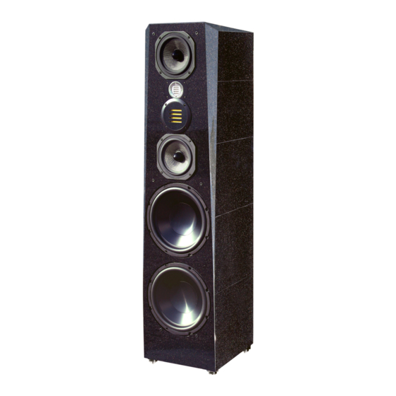
Specifications System Type: 6 drivers, 4 way Tweeter: 1” dual pole neo ribbon, folded Kapton diaphram Midrange: 3" dual pole neo ribbon, vapor deposited kapton diaphram Midwoofer: 2 x 7” Rohacell reinforced Silver Graphite, cast frame Woofer: 1 x 12" spun aluminum diaphragm, rubber surround, total enclosed neo motor, long throw suspension, with cast frame... - Page 23 Notes:...
- Page 24 ©2011 Legacy Audio 3023 E Sangamon Ave. Springfield, IL 62702 Phone: 800-283-4644 Fax: 217-544-1483...
Need help?
Do you have a question about the Focus SE and is the answer not in the manual?
Questions and answers