
Related Manuals for Kalkhoff Fast Pedelec


Summary of Contents for Kalkhoff Fast Pedelec
-
Page 1: User Manual
User Manual English I General User Manual II User Manual | Fast Pedelec III User Manual | Pedelec with centre motor IV User Manual | Pedelec with ont motor Derby Cycle Werke GmbH 2011... - Page 2 Derby Cycle Werke GmbH 2011...
- Page 3 General User Manual English Derby Cycle Werke GmbH 2011...
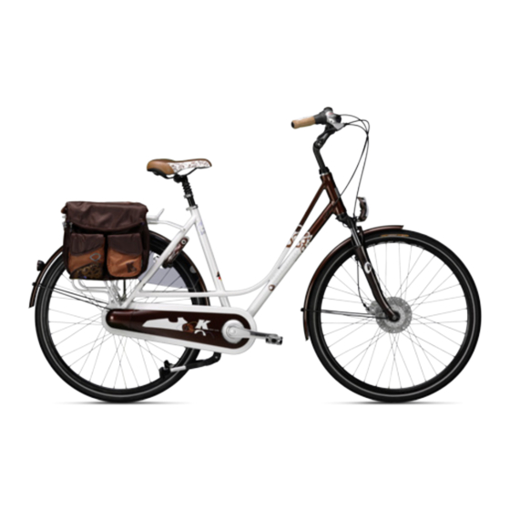
- Page 4 1 The bike and its components Handlebar Handlebar stem Bell Headset Front light 6 Mudguard Fork Front wheel brake 9 Tyres 10 Wheels 11 Bottom bracket 12 Pedals 13 Chain 14 Rear derailleur 14 a Front derailleur 14 b Rear derailleur 15 Rear light 16 Re ector 17 Pannier rack...
-
Page 5: Preface
2 Preface Your bike has been delivered to you lly assembled. If parts of your bike have not been installed, please con- sult your specialist cycle shop. The purpose of this User Manual is to help you use your bike safely in the manner for which is is intended, and en- joy all its bene ts for many years to come. -
Page 6: Table Of Contents
3 Content 9.2.4 Adjusting the saddle angle 1 The bike and its components 9.2.4.1 With a two-bolt seatpost 2 Preface 9.2.4.2 With a seatpost saddle clamp 3 Content 9.2.4.3 With a suspension seatpost 4 Safety information Adjusting the handlebar position Basic safety information 9.3.1 Adjusting / aligning the handlebar height For your own safety... - Page 7 18 Repairing a puncture 20 Bike chain 18.1 Opening the brake 20.1 Maintenance of bike chains 21 Brake, brake levers and brake systems 18.1.1 Opening the cantilever or V-brake 18.1.2 Removing the hydraulic rim brake 21.1 Important information and precautionary measures 18.1.3 Opening the side-pull calliper brake 21.2 Brake lever...
- Page 8 23 Add-on components 27.5 Brake pads 23.1 Pannier rack 27.6 Brake discs 23.1.1 Front pannier rack 27.7 Bike chains or toothed belts 23.1.2 Rear pannier rack 27.8 Chainrings, sprocket wheels and jockey wheels 23.2 Wheel guards / mudguards 27.9 Lamps of lighting set 23.2.1 Re-engaging the safety-release mechanism 27.10 Handlebar tapes and handle grips...
-
Page 9: Safety Information
4 Safety information Information for parents and legal guardians Basic safety information Please read all the warnings and information in this User Manual care lly before using the bike. Keep this User Make sure that your child has been taught, and Manual near your bike for ready reference. -
Page 10: Bike Safety
Be ready to brake, especially if you are not sure what lies ahead or are riding downhill. Bear in mind that with intensive use of your bike wear increases accordingly. Many bike parts, particularly on light sports bikes, are only designed for a speci c period of use. -
Page 11: Intended Use
Trekking bike / all-terrain bike lations (StVZO) in Germany. When performing technical modi cations, bear in mind that electrical components (ATB), if equipped in accordance must only be replaced by type-tested components. with the applicable road tra c licensing regulations 6 Intended use General information Bikes are a means of transportation for one person. -
Page 12: Mountain Bike (Mtb) / Cross Bike
Mountain bike (MTB) / cross bike The bike is exempt om these requirements for the dura- tion of o cially approved cycling events. The manufacturer and cycle shop will not accept liability claims should the bike not be used as intended. This par- ticularly applies for non-observance of the safety informa- tion and damage resulting for example om: •... -
Page 13: Before The Rst Ride
7 Before the rst ride Never in ate the tyres to less than the minimum or more than the maximum speci ed tyre pressure. As a rule of thumb, e.g. when on the road, you can check the tyre pressure as follows: If you press your thumbs into the in ated tyre, there should not be much give in the tyre even if you press hard. -
Page 14: Before Every Ride
8 Before every ride 9 Setting up the bike for the rider Road bikes or mountain bikes can also be supplied with- out pedals. Proceed as follows if you wish to t pedals to your bike yourself: Although a great deal of care has been taken during production and assembly, parts may still come loose or change nction during transportation for example. -
Page 15: Adjusting The Seat Position
Adjusting the seat position Make sure you t or screw in the pedals straight, as 9.2.1 Adjusting the bike saddle otherwise you could damage the thread in the crank arm beyond repair. The seat position is decisive for your well-being and cy- cling performance. -
Page 16: Determining The Correct Saddle Height
Quick-release device When closed, quick-release levers must lie at against the ame, fork and saddle clamp. Make sure that quick-release devices for the hubs point backwards when closed as otherwise they could snag on obstructions when the bike is moving and open. -
Page 17: Adjusting The Saddle Angle
9.2.4.1 With a two-bolt seatpost Some seatposts have two screws for adjusting the sad- The minimum insertion depth is marked on the seat- dle angle, one in ont of and one behind the seat tube. post. If this is not the case, the minimum insertion If you want to tilt the saddle forwards, loosen the rear depth must be 7.5 cm. -
Page 18: With A Suspension Seatpost
9.2.4.3 With a suspension seatpost Bend your upper body towards the handlebar until you have found a position that is comfortable for Suspension seatposts reduce vibrations caused by uneven your back. roads thereby reducing stress on the spinal column. Stretch out your arms towards the handlebar. If you need to adjust the suspension elements in the seat- post, consult your specialist cycle shop. -
Page 19: Adjusting The Handlebar Height With
9.3.4 Adjusting the handlebar position by turning the handlebar Never tighten the handlebar stem if the maximum mark or stop mark is above the top of the sha . If you Loosen the hexagon socket screws on the ont of the cannot nd a mark, insert the handlebar stem into stem. -
Page 20: Adjusting The Handlebar Height With An Adjustable Handlebar Stem
10 Frame 9.3.5 Adjusting the handlebar height with an adjustable handlebar stem The form of the ame depends on the bike type and nc- tion. Frames are manufactured om di erent materials With some types of handlebar stems, you can vary the –... -
Page 21: Headset
11 Headset 12 Fork The ont wheel is held in place by the bike fork. The bike fork consists of two fork blades, the fork crown and steer- ing tube. Headset The headset is the bearing for the bike fork in the ame. If the headset has been properly adjusted, it will turn easily. -
Page 22: Suspension Ame And Suspension Elements
13 Suspension ame and suspension response, but does not strike through if you ride over an obstruction. It must give slightly when you sit on your elements bike. 13.1 Frame with rear suspension 13.2 Care and maintenance If you wish to ride o oad in a particularly sporty manner You can clean your ll-suspension MTB in the usual man- or with a high degree of comfort, you may have opted for a ner. -
Page 23: Bottom Bracket And Cranks
14 Bottom bracket and cranks 16 Wheels Chainrings are wear parts. Their service life depends on various factors, e.g. 16.1 Checking the wheels • maintenance and care, The wheels connect the bike with the surface you are rid- ing on. The wheels are subject to a particularly high level •... -
Page 24: Checking The Rims
17 Tyres and inner tubes triangle backwards and forwards perpendicular to the direction of travel. If you notice that there is play between the bear- 17.1 Tyres ings or if you encounter resistance when turning the wheel, have the hub bearing adjusted by a spe- A large number of di erent tyre types exist. -
Page 25: Tubeless Tyres
Chap- The tyre pressure is equently stated in PSI. ter 30 "Technical data" contains a table which you can use to convert tyre pressures om PSI into bar. Only use tubed tyres on the designated rims. These do not have turned-up edges (rim anges) and instead have a smooth inwards-curving surface onto which the tubed tyre is glued. -
Page 26: Repairing A Puncture
18 Repairing a puncture To in ate an inner tube with a Sclaverand or road valve, proceed as follows: To repair a puncture, you will need the following equip- ment: • Plastic tyre lever • Patches • Rubber solution • Sandpaper •... -
Page 27: Opening The Side-Pull Calliper Brake
18.1.3 Opening the side-pull calliper brake 18.2.2 Removing the rear wheel Open the quick-release lever on the brake arm or If your bike is equipped with derailleur gears, shi brake lever. down to the smallest sprocket. The rear derailleur does not prevent the wheel om being removed in If no quick-release brake mechanisms are tted, this position. -
Page 28: Removing The Tyre And Inner Tube
2. Pull the outer casing out om the outer casing 5. Undo the wheel nuts and put them to one side. holder of the cassette joint, and then remove the Remove the lock washers om the wheel axle. inner cable om the slit in the bracket. 6. -
Page 29: Fitting The Tyre And Inner Tube
18.5 Fitting the tyre and inner tube 18.6 Fitting the wheel Please note that the work steps described here are for a speci c example. Please observe the information om the relevant manu- facturer or consult your specialist cycle shop. Make sure that foreign bodies do not enter the inside of the tyre. - Page 30 2. Fit the xing washers onto both sides of the hub axle. Turn the shi ing arm until the projections on the xing washers engage with the slits in the Counter the clamp nut with a 10 mm spanner when dropouts.
- Page 31 Installing the shi ing cable with hub gears Attach the inner cable to the pulley as shown in the illustration, pass the inner cable through the slit in Bring the cable around to the cassette joint pulley, the cassette joint bracket, and then insert the end hold so that the inner cable xing nut is facing to of the outer casing securely into the outer casing the outside (toward the dropout), and then slide...
-
Page 32: Bike Gears
19 Bike gears Check that the inner cable is correctly seated inside the pulley guide. 19.1 Derailleur gears This User Manual describes the handling of typical, com- mercially available gear-shi components for MTB, ATB, cross and road bikes. Separate instructions are provided for other components on the CD or on the web pages of the CJ-8S20 CJ-8S20... -
Page 33: Operating The Shi Ing Lever
19.1.1 Operating the shi ing lever The bike chain must not be on the smallest chainring 19.1.1.1 Shi ing lever on road bike at the ont and the small outer rear sprocket wheel simultaneously. The bike chain must not be on the Shimano shi ing lever largest chainring at the ont and large inner sprocket wheel at the rear simultaneously. - Page 34 Operating the rear derailleur shi ing lever Lever a: Shi to a larger sprocket. When lever a is pressed, lever b moves with it. How- Lever a engages in positions 1, 2 and 3. ever, you should avoid putting any pressure on lever b in doing so.
- Page 35 Operating the ont derailleur lever with trimming Trimming (noise prevention) (noise prevention), optional Depending on the position of the chain a er shi ing, it may rub against the outer chain guide plate or inner chain Gear shi ing operations guide plate of the ont derailleur and produce noise.
- Page 36 TRIMMING CHAIN POSITION INDICATION LEVER OPERATION FRONT DERAILLEUR MOVEMENT large chainring Chain in contact with outer chain guide plate Lever Trimming Outer chain guide plate before trimming a er trimming smaller sprockets Front derailleur movement Middle chainring Smaller sprockets Small chainring Click-in position (contact)
-
Page 37: Shi Ing Lever On Mtb, Trekking And Touring Bike
SRAM shi ing lever Setting the swivel range The range of the shi ing and brake lever pivoting move- ment can be adjusted individually to suit the size of your hand. XX° 0° X° First, set the shi ing lever range then adjust the Click Click brake lever until the brake lever limit stop makes... - Page 38 Gear shi complete stroke Click-in position Trimming operation Click-in position H b l (B) Lever Lever Shi ing om a large to a smaller chainring Press lever b once to move the chain om a large to a When lever b is operated, there is one click where trim- smaller chainring.
- Page 39 Rear derailleur The adjustment screw may also be on the shi ing lever or on the ame. Have your specialist cycle shop carry out maintenance Adjustment screw on the derailleur gears, or replace or adjust them. Precision adjustment / rear derailleur Operate the shi ing lever to shi the chain om the small- est sprocket to the second sprocket.
-
Page 40: Hub Gears
Cleaning Whenever possible, avoid using cleaning agents on The gears can be changed when the pedals are turn- the chain. If you use cleaning agents, such as rust ing. Very occasionally, the hub may produce a harm- remover, this may wash lubricant out of the chain less noise which is caused by its internal cogs and which could lead to mal nctions. -
Page 41: Adjusting Gears With Shimano Hub Gears
19.2.2 Adjusting gears with Shimano hub Turn the cable adjustment bolt on the shi lever to align the marking lines. Next, set the Revo-shi gears lever om position 4 to position 1 then back to position 4. Check that the yellow marking lines still Example shown is a 7/8-speed hub. -
Page 42: Bike Chain
20 Bike chain There are two types of bike chain: Tighten all screws to the prescribed torque as other- wise screws could shear o and components could • A wide bike chain (½ × 1 / 8") for hub gears and come loose or detach altogether (see Chapter 30 "Technical data"). -
Page 43: Brake, Brake Levers And Brake Systems
21 Brake, brake levers and brake Rubber brake blocks and brake pads must not come into contact with oil or grease. If the rubber brake blocks and systems brake pads come into contact with oil or grease, this dras- tically reduces their braking performance and they must This User Manual describes the maintenance and handling be replaced. -
Page 44: Brake Lever
21.2 Brake lever 21.3.1 Drum and roller brakes With the roller brake or drum brake, the braking force is transmitted via a cable om the hand brake lever to the 21.2.1 Standard brake lever brake system. If applied continuously for an extended period, roller brakes or drum brakes become very hot. -
Page 45: Back-Pedal Brake
21.3.2 Back-pedal brake With back-pedal brakes the braking force is transmitted Avoid operating the back-pedal brake continuously on by the foot via the chain to the brake system. If applied long descents as the internal components of the brake continuously for an extended period, back-pedal brakes system can become extremely hot which reduces brak- become very hot. -
Page 46: Rim Brakes
21.4 Rim brakes 21.4.2 Adjusting the brake-pad clearance in relation to the rim Turn the cable adjustment bolt to adjust the clearance between the brake pad and the rim. Turn the bolt inwards (clockwise) to increase the brake-pad clearance. Turn the V-brakes produce an extremely high braking force. -
Page 47: Wear Of Brake Pad
21.4.3 Wear of brake pad If required, you can readjust the rebound force via the spring adjustment screw so that both brake arms move Most brake pads for rim brakes come with grooves or symmetrically. Once you have done this, check that the notches. -
Page 48: Hydraulic Disc Brake
If you hear unusual noises when braking, the brake blocks If the brake disc is worn, cracked or bent it must be re- may have reached their wear limit. Allow the brakes to placed. Have this work carried out by a professional bike cool down then check the brake block depth. -
Page 49: Vapour Bubble Formation
21.5.2 Vapour bubble formation Vapour bubble formation can occur if the brakes Brake pads and brake blocks are wear parts. Have the are operated continuously for some time, e. g. dur- brake pads of hydraulic disc brakes checked regularly, ing a long steep descent. and replaced if necessary, by a professional bike Instead of applying gentle pressure continuously workshop. -
Page 50: Lighting System
22 Lighting system 22.3 Generator / dynamo The dynamo produces the energy required to operate the ont and rear lights. There are di erent types of dynamos. In some EU countries, only lighting systems that are 22.3.1 Sidewall dynamo prescribed by national legislation (the Road Tra c Li- censing Regulations (StVZO) in Germany for example) and have been approved for use may be installed on bikes. -
Page 51: Hub Dynamo
22.4 Failure of the lighting system 22.3.2 Hub dynamo The hub dynamo is inside the hub of the ont wheel. The hub dynamo is highly e cient, and the wear is extremely low. If the lighting system fails or develops a fault when riding in the dark this could cause a serious accident. -
Page 52: Add-On Components
23 Add-on components 23.1.1 Front pannier rack 23.1 Pannier rack The pannier racks on the bike satis the standard EN 14873. The load-carrying capacity of the pannier rack falls into one of four possible categories: 5 kg, 10 kg, 18 kg and 25 kg. -
Page 53: Wheel Guards / Mudguards
If you notice that a wheel guard is damaged, always re- place it before using the bike again. If you carry pannier bags or other loads on the pan- nier racks, make sure they are securely attached. 23.2.1 Re-engaging the safety-release Make sure that nothing can become caught in the spokes and the turning wheels. -
Page 54: Accessories And Equipment
24 Accessories and equipment Never attach the child seat to the bike handle- bars directly as it will not be possible to steer the bike safely. Do not use a suspension saddle if you are car- rying a child in a child seat behind the saddle. The child's ngers could be crushed. -
Page 55: Bike Stand
24.2 Bike stand 24.4 Bike basket The xing for the basket must not damage the handle- Never leave your child sitting unattended in the bar or handlebar stem. child seat when you park your bike. The bike Attach the basket so as not to cover the ont could fall over and severely injure the child. -
Page 56: Bike Carriers For Mounting On Roof And Rear Of Car
25 Bike carriers for mounting on 26 Carbon components roof and rear of car Carbon is a speci c material that requires special han- dling and care when setting up and carrying out mainte- nance on the bike as well as when riding and also during transportation and storage. -
Page 57: Visual Inspection
Inspect the following components and areas regularly (at ranty void. This kind of adapter should only be least every 100 km) for cracks, actures or changes in tted by a specialist cycle shop. surface appearance. Furthermore, if you come o the bike •... -
Page 58: Carbon Wheels
26.7 Carbon wheels ment of pannier racks, trailers and other xtures are not permitted due to the risk of breakage. Surface wear, change of surface, e. g. due to heat pro- duced when braking, abrasion of brake blocks, wheel hub 26.10 Splinters or their anks If you are using a bike with carbon rims, bear in mind that... -
Page 59: Care And Maintenance Of The Bike
27 Care and maintenance of the bike Have defective parts replaced before you ride the bike again. Touch up damaged paintwork. 27.1 Care Treat all parts that are susceptible to corrosion more equently than other parts with preservatives and care products, especially during the winter and in aggressive Do not allow care products or oils to come into con- environments such as coastal regions as otherwise your... -
Page 60: Tyres
27.3 Tyres 27.6 Brake discs Due to their nction, bike tyres are subject to wear. This Brake discs also wear out as a result of intensive braking, depends on how the bike is used and the rider can in u- or during the course of time. -
Page 61: Handlebar Tapes And Handle Grips
27.10 Handlebar tapes and handle grips 27.15 Sliding bearings and bearings for ll-suspension ames, suspension Handlebar tapes and handle grips are subject to nction- forks or other suspension elements related wear and therefore may need to be replaced. The suspension components on the bike, particularly the Check regularly that the handles are securely sliding bearings, bearings and suspension elements, must seated. -
Page 62: Regular Inspections
28 Regular inspections Have the following components readjusted: • headset, As the spokes settle, the length of the brake and shi ing cables increases and the bearings will run in during the • gearshi , rst kilometres on the bike, you will have to have an ini- •... -
Page 63: Link List
29 Link list a er 3000 kilometres If necessary, the You can obtain important information on your bike and its components via these links. The relevant user manual • hubs, is normally provided on the manufacturer's web pages, in • headset, addition to important tips for use and making settings. -
Page 64: Technical Data
30 Technical data 30.1 Maximum permitted gross weight of bike The maximum permitted gross weight of the bike compris- es the weight of the bike, the weight of the rider and the weight of the luggage. It also includes the laden weight of a trailer. -
Page 65: Maximum Permitted Loading Of Pannier Rack
30.2 Maximum permitted loading Observe the minimum screw-in depth. For hard aluminium alloys this is at least 1.4 times the screw diameter (e.g. of pannier rack nominal diameter M 5 × 1.4 = 7 mm). Whenever possible, you should tighten all safety-relevant screw connections using a torque wrench. - Page 66 SCREW CONNECTION THREAD TIGHTENING TORQUE NM General Crank arm, steel M8x1 Crank arm, alu M8x1 Pedal 9 / 16" Axle nuts, ont gen. Axle nuts, rear gen. Stem expander bolt wedge Stem, A-head, angle adjustment Stem, A-head, handlebar clamping xture M5 / M6 / M7 M5: 5 / M6: 10 / M7: 14 Stem, A-head, head tube M5 / M6 / M7...
-
Page 67: General Tightening Torques For Screw Connections
30.5 Lighting set 30.3.1 General tightening torques for screw connections Depending on which type of lighting set is tted on your bike you may require di erent spare lamps. The following The screw grade, e.g. 8.8, is embossed in the screw head. table shows which bulbs you require. -
Page 68: Warranty Conditions
31 Warranty conditions • Non-compatible add-on components that were not part of the scope of delivery at the time the prod- Chapter 27 "Care and maintenance of the bike" Read uct was handed over, or damage caused by unpro- care lly. Comply with the inspection and maintenance fessional installation of these add-on components. - Page 69 I General User Manual...
- Page 70 We hope you thoroughly enjoy using your your new bike! Copyright © 2011 Derby Cycle Werke GmbH Reproduction in whole or in part is not permitted without the consent of Derby Cycle Werke GmbH. Subject to misprints, errors and technical modi cations.
- Page 71 User Manual Fast Pedelec English Derby Cycle Werke GmbH 2011...
- Page 72 Charger LCD control panel Battery Battery lock Motor unit Control panel Charger II User Manual Fast Pedelec...
- Page 73 You can decide yourself how much you want to use it. The purpose of this User Manual is to help you get the most out of your fast Pedelec and WARNING about possible physical injury, in- use it correctly.
- Page 74 Content 1 Quick start 4.1.10 Battery charge state indicator 2 Fast Pedelec / ndamental legal principles 4.1.11 Power output indicator Legal principles 4.1.12 Switching the light on and o 2.1.1 Meaning for the rider 5 Assistance by the electric motor 2.1.2 Fast Pedelecs and cycle paths...
- Page 75 8.1.6 Additional possible sources of errors 9 Cleaning 10 Warnings 11 Technical data 12 Replacing components of the fast Pedelec 12.1 Components that can only be replaced by equivalent parts or approved parts 12.2 Spare tyres 12.3 Components that do not require a...
- Page 76 II User Manual Fast Pedelec...
-
Page 77: Quick Start
8. Push the "On / O " button on the control panel on the handlebar. Wait for 2 seconds before turn- ing the pedals. The drive system requires this time II User Manual Fast Pedelec... -
Page 78: Fast Pedelec / Ndamental Legal Principles
The fast Pedelec is classed om a legal point of view as a L1e moped. In some EU countries, like all other bikes, If you use your fast Pedelec as you would use a bike, i.e. it must comply with certain regulations, the Road Tra c without assistance om the electric motor, you can use Licensing Regulation in Germany (StVZO) for example. -
Page 79: Charging The Battery
4. Make sure the battery is rmly in place. Tilt to remove You should now remove the key and keep it in a safe place to prevent it om breaking o or being lost. II User Manual Fast Pedelec... -
Page 80: Lcd Control Panel
All recording of data (trip, actual journey length, average speed, top speed, total journey length) starts as soon as you switch the control panel on and stops when you switch it o . II User Manual Fast Pedelec... -
Page 81: Changing The Assist Level
To do this, press the button that switches the lights on. The drive remains in "NO ASSIST / no assistance" mode. Now you cannot change the assist level. II User Manual Fast Pedelec... -
Page 82: Reprogramming The Language, Wheel Circumference And Lcd Contrast
▲button ▼button ▲button display (setting selection) (setting selection) * ▲button refers to the ▲button for assist level selection * ▼button refers to the▼button for assist level selection total mileage (1st digit) ▼button ▲button (setting selection) II User Manual Fast Pedelec... -
Page 83: Automatic Switch-O
4.1.11 Power output indicator The power output indicator shows the actual power output being requested and the actual power consumption in 6 stages (bars). This indicator helps you save power when riding which means you can travel rther. II User Manual Fast Pedelec... -
Page 84: Switching The Light On And O
If you are using the assistance and press the light switch, maximum motor output. this switches the lighting of the fast Pedelec on and o . • The assist level you have selected If you are riding with the lights on and switch o the system, the lights also switch o automatically. -
Page 85: Distance
Discharge curve at low temperatures Discharge capacity at low temperatures Di erence between nor- mal and low temperature Discharge capacity at normal temperatures Discharge capacity (Ah) or hours of use Rate of discharge at di erent temperatures II User Manual Fast Pedelec... -
Page 86: Riding Your Pedelec E Ciently
• A new battery costs roughly 599 euros. revolution. • You can cover 48 km on average with one battery • Technical condition of your fast Pedelec charge. Make sure the tyre pressure is correct. If you ride • You can charge the battery roughly 1,100 times. -
Page 87: Battery
300 the battery out of its holder and transport it watt motor. separately. The battery should ideally be stored for longer periods charged to 75% of its capacity at a tem- perature of +10 °C. II User Manual Fast Pedelec... -
Page 88: Battery Information System
If you press the "Push" button for longer than ve sec- onds, the LEDs show the current capacity of the battery. DISPLAY CAPACITY 100 – 80% 80 – 60% 60 – 40% 40 – 20% 20 – 0% Capacity indicator II User Manual Fast Pedelec... -
Page 89: Service Life And Warranty
• the number of charge cycles and • the age of the battery. When you have lly charged and discharged your battery 1,100 times, it will still have 60% of its initial capacity, providing it has been well looked a er: II User Manual Fast Pedelec... -
Page 90: Charger
Do not cover the charger or place any objects on your Pedelec replaced with genuine parts. This makes it as otherwise it could overheat and catch re. it safer for you and avoids problems when processing warranty claims. II User Manual Fast Pedelec... -
Page 91: Problems / Solutions: Flash Patterns And Their Meaning
2 seconds. If "E1" is displayed the distance covered will not be recorded. It will therefore no longer be possible to adjust the assistance control and the power assist will no longer work. II User Manual Fast Pedelec... -
Page 92: Display "E9
If this does not happen, contact your specialist When wiping down the battery, be care l not to touch and cycle shop. connect the contacts on the underside. This could cause the battery to switch o . II User Manual Fast Pedelec... -
Page 93: Warnings
Take this into account when familiarising yourself with your fast Pedelec. Bear in mind that the Pedelec motor can heat up on long ascents. Be care l not to touch it with your hands, feet or legs as you could burn your- self. -
Page 94: Technical Data
– – – – Possible applications of batteries 110% 105% 100% – 20 °C – 10 °C 0 °C 10 °C 20 °C 30 °C 40 °C 50 °C Capacity curve at di erent temperatures II User Manual Fast Pedelec... -
Page 95: Replacing Components Of The Fast Pedelec
Pedelec replaced by equivalent parts or approved parts As your fast Pedelec is a Category L1e moped. As is the case with other motor vehicles in Germany, it is necessary • Frame to obtain a permit om the Federal Motor Transport Au- •... -
Page 96: Spare Tyres
( . bar) Crazy Bob Performance wired kg ( bar) Energizer Active wired kg ( bar) Energizer Active wired kg ( bar) Energizer Active wired * max. load with speci ed tyre pressure II User Manual Fast Pedelec... -
Page 97: Components That Do Not Require A
• Seatpost • Bell: Can be replaced with an equivalent bright- sounding bell. • Rear-view mirror: Can be replaced with a di erent type-ap- proved rear-view mirror. • Chain • Headset • Inner tube • Hubs II User Manual Fast Pedelec... - Page 98 We hope you thoroughly enjoy using your new fast Pedelec. Copyright © 2011 Derby Cycle Werke GmbH Reproduction in whole or in part is not permitted without the consent of Derby Cycle Werke GmbH. Subject to misprints, errors and technical...
- Page 99 User Manual Pedelec with centre motor English Derby Cycle Werke GmbH 2011...
- Page 100 Charger LCD control panel LED control panel Battery Battery lock Motor unit Control panel Charger III User Manual Pedelec with centre motor...
- Page 101 Dear Customer, In addition to texts and tables, the User Manual contains the following symbols that denote important information Thank you for choosing a Pedelec (pedal electric cycle) or dangers. om us. This bike is equipped with an electric drive that assists you when you are cycling.
- Page 102 Content EC Declaration of Conformity 4.2.1.8 Automatic switch-o 1 Quick start 4.2.1.9 Measurement and display ranges 14 2 Pedelec / ndamental legal principles 4.2.1.10 Battery charge state indicator Meaning for the rider 4.2.1.11 Power output indicator Pushing assistance 5 Assistance by the electric motor 3 Charging the battery Operating principle of assistance Distance...
- Page 103 8 Troubleshooting Problems / solutions: Flash patterns and their meaning 8.1.1 Pedelec with LED control panel 8.1.2 Pedelec with LCD control panel 8.1.2.1 No display 8.1.2.2 Battery charge state indicator ashing or not visible 8.1.2.3 Display “E1” 8.1.2.4 Display “E9” 8.1.2.5 Assistance control indicator ashing...
-
Page 104: Ec Declaration Of Conformity
EC Declaration of Conformity The manufacturer: Derby Cycle Werke GmbH Siemensstrasse 1 – 3 49661 Cloppenburg, Germany Telephone: +49 (0) 4471 / 966-0 hereby declares that the following products: Product description: Kalkho Pedelec Model designation: Pro Connect C11 Disc, Pro Connect C8 Disc, Pro Connect C8, Pro Connect C9, Agattu XXL C8, Agattu F8, Agattu C8, Agattu C7, Agattu C3, Tasman Tour C8, Tasman City F8, Tasman City C8, Connect Lady F8, Connect Lady C8, Sahel... -
Page 105: Quick Start
1 Quick start If your Pedelec is equipped with an LED control panel: 1. Charge the battery completely before riding for Push the "Power" button on the control panel on the handlebar. Wait for 2 seconds before turning the rst time. the pedals. -
Page 106: Pedelec / Ndamental Legal Principles
2 Pedelec / ndamental legal Pushing assistance principles You can have your specialist cycle shop t what is known as "pushing assistance" to your bike. The essential idea behind the Pedelec is not only to be able to cover greater distances more quickly, but also more comfortably. -
Page 107: Charging The Battery
3 Charging the battery 3.2.1 Charging operation Before charging the battery, read the information on the To charge the battery, you have to take it out of the holder charger care lly. on the Pedelec. 1. Take the charger provided out of its packaging and plug the mains plug into a socket (230 V, ob- Carry handle serve type plate on the charger). -
Page 108: Control Panel (Display)
4 Control panel (display) You can speci the power assist level via the "Mode" buttons. The LEDs next to the top button show how much assistance the motor is currently providing. LED control panel All three LEDs light up for two seconds when the power is switched on. -
Page 109: Automatic Switch-O
The assistance reduces in stages; when you reach "LOW" (the lowest assist level) it jumps back to "HIGH" (the high- est assist level). 4.1.1 Automatic switch-o If you stop and do not move your Pedelec for 10 minutes, the system switches o automatically. If you subsequently want to ride using the assistance, you will have to switch it back on via the control panel. -
Page 110: Function Of Lcd Control Panel
4.2.1 Function of LCD control panel 4.2.1.1 On / O button Press the "On / O " button to switch on the control panel and drive. Reduce power assist The assist level that was active at the time the control panel was switched o is automatically reinstated. -
Page 111: Reprogramming The Language, Wheel Circumference And Lcd Contrast
4.2.1.7 Reprogramming the language, wheel circumference and LCD contrast Normal display Display mode Settings mode Display selector button & ▼button for 3 sec. Press light button to apply the settings ▼ button (setting selection) ▼ button ▼ button ▼ button ▼... -
Page 112: Automatic Switch-O
4.2.1.8 Automatic switch-o DISPLAY BATTERY CHARGE STATE If you stop your Pedelec and it does not move for 10 min- 80 – 100% utes, the system switches o automatically. If you want to 60 – 80% use the assistance again, you will have to switch it back 40 –... -
Page 113: Assistance By The Electric Motor
5 Assistance by the electric motor • The assist level you have selected With the "high assist level / HIGH" the power deliv- ered by the motor is double your own e ort (1 : 2). With the "medium assist level / MID", the power delivered by the motor matches your own e ort (1 : 1). -
Page 114: Distance
Distance • Selected assist level If you want to cover a large distance assisted by The distance you can travel using the power assist with the motor, select the lower gears, i.e. the ones the battery lly charged depends on several factors: that are easier to pedal. -
Page 115: Riding Your Pedelec E Ciently
Riding your Pedelec e ciently • Technical condition of your Pedelec Make sure the tyre pressure is correct. If you ride You can monitor and in uence the cost of your journeys your bike with too little air in the tyres, this can with the Pedelec yourself. -
Page 116: Battery
6 Battery Your battery is a lithium cobalt battery, the ideal type of Observe the following points to increase the service lithium-ion (Li-ion) battery for this application. One of the life of your Pedelec battery: main bene ts of this type of battery is its low weight com- Make sure that the battery is lly charged before bined with a high capacity. -
Page 117: Battery Information System
Battery may be Long charging times damaged Optimum temperature range for charging operation -10 °C 0 °C 10 °C 20 °C 30 °C 40 °C 50 °C Charging times at di erent temperatures Battery information system 6.4.1 Checking the battery charge state Press the "Push"... -
Page 118: Service Life And Warranty
Check there is su cient charge in the battery for The service life of the battery depends on di erent factors. the journey you intend to make before setting o . The most important wear-relevant factors are • the number of charge cycles and In winter the distance you can normally cover with the battery operating normally is less. -
Page 119: Charger
7 Charger 8 Troubleshooting Read the two stickers on the charger before using it for the The control panel also indicates when faults and technical rst time. errors are present. If a fault occurs, the LEDs ash in a speci c pattern and with a speci c rhythm. -
Page 120: Problems / Solutions: Flash Patterns And Their Meaning
Problems / solutions: Flash patterns and their meaning If a problem occurs in the electrical system of your Pe- delec, you should initially try to solve it by referring to the following list which describes possible causes of errors and o ers solutions. If the fault persists, consult your specialist cycle shop. -
Page 121: Pedelec With Lcd Control Panel
8.1.2 Pedelec with LCD control panel 8.1.2.3 Display "E1" If "E1" is displayed, the following cause/solution may 8.1.2.1 No display apply: If nothing is shown in the LCD display, one of the follow- Error code ing reasons/solutions may apply: Is the battery su ciently charged? Charge the battery. -
Page 122: Assistance Control Indicator Ashing
8.1.2.5 Assistance control indicator ashing When wiping down the battery, be care l not to touch and connect the contacts on the underside. This could cause If the assistance control indicator is ashing although the the battery to switch o . battery charge is su cient, the following cause and solu- tion may apply: 10 Warnings... -
Page 123: Technical Data
11 Technical data MOTOR PANASONIC LI ION BATTERY Brushless electric motor Voltage 25.2 V Output 250 watts Capacities 8 / 10 / 12 / 18 Ah Maximum torque at drive pinion Energy quantity 13 Nm 200 / 250 / 300 / 450 Wh Gross weight of electric drive, battery, 7.8 kg (12 Ah battery) control unit... - Page 124 We hope you thoroughly enjoy using your new Pedelec! Copyright © 2011 Derby Cycle Werke GmbH Reproduction in whole or in part is not permitted without the consent of Derby Cycle Werke GmbH. Subject to misprints, errors and technical modi cations.
- Page 125 User Manual Pedelec with ont motor English Derby Cycle Werke GmbH 2011...
- Page 126 Motor LED control panel Charger Battery Battery lock Motor unit Control panel Charger IV User Manual Pedelec with ont motor...
- Page 127 Dear Customer, In addition to texts and tables, the User Manual contains the following symbols that denote important information Thank you for choosing a Pedelec (pedal electric cycle) or dangers. om us. This bike is equipped with an electric drive that assists you when you are cycling.
- Page 128 IV User Manual Pedelec with ont motor...
- Page 129 Content EC Declaration of Conformity 6 Battery 1 Quick start Straightforward charging 2 Pedelec / ndamental legal principles High degree of safety due to battery management Meaning for the rider Straightforward storage Pushing assistance Battery information system 3 Charging the battery 6.4.1 Checking the battery charge state 6.4.2 Checking the battery capacity Service life and warranty...
-
Page 130: Ec Declaration Of Conformity
EC Declaration of Conformity The manufacturer: Derby Cycle Werke GmbH Siemensstrasse 1 – 3 49661 Cloppenburg, Germany Telephone: +49 (0) 4471 / 966-0 hereby declares that the following products: Product description: Kalkho Pedelec Model designation: Pro Connect C11 Disc, Pro Connect C8 Disc, Pro Connect C8, Pro Connect C9, Agattu XXL C8, Agattu F8, Agattu C8, Agattu C7, Agattu C3, Tasman Tour C8, Tasman City F8, Tasman City C8, Connect Lady F8, Connect Lady C8, Sahel... -
Page 131: Quick Start
1 Quick start when no force is applied to the pedals to adjust the power sensor correctly. 1. Charge the battery completely before riding for 9. The intermediate power-assist mode appears the rst time. on the display panel of the LED control panel. Press the "Mode"... -
Page 132: Pedelec / Ndamental Legal Principles
2 Pedelec / ndamental legal Pushing assistance principles You can have your specialist cycle shop t what is known as "pushing assistance" to your bike. The ndamental idea behind the Pedelec is not only to be able to cover greater distances more quickly, but also do this comfortably. -
Page 133: Charging The Battery
3 Charging the battery 3.2.1 Charging operation Before charging the battery, read the information on the To charge the battery, you have to take it out of the holder charger care lly. on the Pedelec. 1. Take the charger provided out of its packaging and plug the mains plug into a socket (230 V, ob- Carry handle serve type plate on the charger). -
Page 134: Led Control Panel (Display)
4 LED control panel (display) You can speci the power assist level via the "Mode" but- tons. The LEDs next to the top button show the level of assistance you are currently receiving om the motor. All three LEDs light up for two seconds when the power is switched on. -
Page 135: Switching The Light On And O
The assistance reduces in stages; when you reach "LOW" (the lowest assistance level) it jumps back "HIGH" (the highest assistance level). 4.2.1 Switching the light on and o Button for lights Press the button shown above to switch the Pedelec light- ing on and o . -
Page 136: Assistance By The Electric Motor
5 Assistance by the electric motor Distance The distance you can travel using the power assist with the battery lly charged depends on several factors: Operating principle of assistance • Ambient temperature The motor provides support as soon as you switch the as- If it is colder, you will travel a shorter distance sistance on and start pedalling. -
Page 137: Riding Your Pedelec E Ciently
Discharge curve at normal temperatures Discharge curve at low temperatures Discharge capacity at low temperatures Di erence between nor- mal and low temperature Discharge capacity at normal temperatures Discharge capacity (Ah) or hours of use Rate of discharge at di erent temperatures Riding your Pedelec e ciently •... -
Page 138: Battery
6 Battery Your battery is a lithium cobalt battery, the ideal type of Observe the following points to increase the service lithium-ion (Li-ion) battery for this application. One of the life of your Pedelec battery: main bene ts of this type of battery is its low weight com- Make sure that the battery is lly charged before bined with a high capacity. -
Page 139: Battery Information System
Battery may be Long charging times damaged Optimum temperature range for charging operation -10 °C 0 °C 10 °C 20 °C 30 °C 40 °C 50 °C Charging times at di erent temperatures Battery information system 6.4.1 Checking the battery charge state Press the "Push"... -
Page 140: Service Life And Warranty
Check there is su cient charge in the battery for When you have lly charged and discharged your battery the journey you intend to make before setting o . 1,100 times, it will still have 60% of its initial capacity, providing it has been well looked a er: In winter the distance you can normally cover with the battery operating normally is less. -
Page 141: Charger
7 Charger 8 Troubleshooting Read the two stickers on the charger before using it for the The control panel also indicates when faults and techni- rst time. cal errors are present. If a fault occurs, the LEDs ash in a speci c pattern and with a speci c rhythm. -
Page 142: Problems / Solutions: Flash Patterns And Their Meaning
Problems / solutions: Flash patterns and their meaning If a problem occurs in the electrical system of your Pe- delec, you should initially try to solve it by referring to the following list which describes possible causes of errors and o ers solutions. If the fault persists, consult your specialist cycle shop. -
Page 143: Removing The Ont Wheel
9 Removing the ont wheel To open the white connector, push a sharp object (tip of a key or ball point pen) down onto the an- As the motor is built into the ont wheel, you must per- gled surface of the snap-in mechanism, as shown form the following steps before you can remove the ont below. -
Page 144: Cleaning
10 Cleaning Undo the two hexagon socket screws on the le behind the fork using a 5 mm Allen key. You need to turn them anticlockwise. Remove the battery before you clean your Pedelec. Apply a max. tightening torque of 9.5 Nm to these screws when putting the wheel back on We recommend you clean your Pedelec with a damp cloth, a sponge or a brush. -
Page 145: Warnings
11 Warnings Bear in mind that the Pedelec motor can heat up on long ascents. Be care l not to touch it with your hands, feet or legs as you could burn your- self. The Pedelec operates using low voltage (25.2 volts). -
Page 146: Technical Data
12 Technical data MOTOR PANASONIC LI ION BATTERY Hub motor with planetary gear Voltage 25.2 V Output 250 watts Capacities 8 / 10 / 12 / 18 Ah Maximum torque 16 Nm Energy quantity 200 / 250 / 300 / 450 Wh Gross weight of electric drive, battery, 7.0 kg (12 Ah battery) control unit... - Page 147 IV User Manual Pedelec with ont motor...
- Page 148 We hope you thoroughly enjoy using your new Pedelec! Copyright © 2011 Derby Cycle Werke GmbH Reproduction in whole or in part is not permitted without the consent of Derby Cycle Werke GmbH. Subject to misprints, errors and technical modi cations.
Need help?
Do you have a question about the Fast Pedelec and is the answer not in the manual?
Questions and answers