Table of Contents
Advertisement
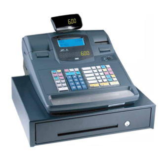
TEC Electronic Cash Register
MA-600 SERIES
Maintenance Manual
Original
Dec., 2005
(Revised
Dec., 2006)
NOTE:
Model names that end with "-R" are RoHS compliant models. If "-R" is not
attached, that model is non RoHS compliant.
Never install non RoHS compliant optional equipment or parts on a RoHS
compliant machine which is supposed to be used in the countries that enforce
the RoHS directive, as doing this is legally prohibited.
Document No. EO18-11006A
PRINTED IN JAPAN
Advertisement
Table of Contents

Related Manuals for TEC MA-600 SERIES


Summary of Contents for TEC MA-600 SERIES
- Page 1 TEC Electronic Cash Register MA-600 SERIES Maintenance Manual Document No. EO18-11006A Original Dec., 2005 (Revised Dec., 2006) NOTE: Model names that end with “-R” are RoHS compliant models. If “-R” is not attached, that model is non RoHS compliant. Never install non RoHS compliant optional equipment or parts on a RoHS compliant machine which is supposed to be used in the countries that enforce the RoHS directive, as doing this is legally prohibited.
- Page 2 WARNING! Follow all manual instructions. Failure to do so could create safety hazards such as fire or electrocution. NOTES: 1. Manual instructions must be followed when installing option kits or adding cables to avoid system failures and to insure proper performance and operation. 2.
-
Page 3: Table Of Contents
EO18-11006A TABLE OF CONTENTS Page 1. UNPACKING ......................1- 1 Procedure ........................1- 1 Checks..........................1- 1 2. INSTALLATION PROCEDURE FOR OPTIONAL EQUIPMENT........ 2- 1 KRDC-600-QM-R (for QP model only) ................2- 1 3. DIAGNOSTIC TEST OPERATION ................3- 1 Diagnostic Test Operation List ..................3- 1 Print Test (“H”... - Page 4 2. The contents of this manual may be changed without notification. 3. Please refer to your local Authorised Service representative with regard to any queries you may have in this manual. Copyright © 2005 by TOSHIBA TEC CORPORATION All Rights Reserved 570 Ohito, Izunokuni-shi, Shizuoka-ken, JAPAN...
-
Page 5: Unpacking
1. UNPACKING EO18-11006A 1.1 Procedure UNPACKING Procedure CAUTION! 1. When newly setting up the MA-600, plug the power cord to charge the ECR for 48 hours or more. 2. When using the MA-600 not electrified for 1 month or more, plug the power cord to charge the ECR for 48 hours or more and then perform a RAM clear, resulting that the ECR performs normally. -
Page 6: Installation Procedure For Optional Equipment
WARNING! Be sure to unplug the power cord before installing any optional equipment. KRDC-600-QM-R (for QP model only) This kit is used for connecting the RD-G8-C-QM-R Remote Drawer to the MA-600 series. • Packing List Remote Drawer Harness (1 pc.) Connector Label (1 pc.) - Page 7 2. INSTALLATION PROCEDURE FOR OPTIONAL EQUIPMENT EO18-11006A 2.1 KRDC-600-QM-R (for QP model only) Disconnect the drawer cable from the bottom of Drawer Cable the ECR. Attach the connector label beside the drawer connector as shown in the figure. Connector Label Connect the remote drawer harness to the remote drawer cable.
- Page 8 2. INSTALLATION PROCEDURE FOR OPTIONAL EQUIPMENT EO18-11006A 2.1 KRDC-600-QM-R (for QP model only) Secure the remote drawer harness onto the bottom of the ECR with the option cable clamp and screw as shown in the figure. At this time, secure the earth wire of the remote drawer Earth Wire harness together.
-
Page 9: Diagnostic Test Operation
3. DIAGNOSTIC TEST OPERATION EO18-11006A 3.1 Diagnostic Test Operation List DIAGNOSTIC TEST OPERATION Diagnostic Test Operation List [X] = [@/FOR] Diagnostic Function Key Operation Print Test (“H” & All characters) 80 [X] 1 [AT/TL] Display Test 80 [X] 2 [AT/TL] ROM Test 80 [X] 3 [AT/TL] RAM Test... -
Page 10: Print Test ("H" & All Characters)
3. DIAGNOSTIC TEST OPERATION EO18-11006A 3.2 Print Test (“H” & All Characters) Print Test (“H” & All Characters) (1) Contents A print test is performed. This test prints “H”s and all characters. (2) Operation Mode Lock: BLIND Key Operation: 80 [X] (or [@/FOR]) 1 [AT/TL] (3) Print Format Store Name Logo 10-31-2005 MON... -
Page 11: Display Test
3. DIAGNOSTIC TEST OPERATION EO18-11006A 3.3 Display Test Display Test (1) Contents A display test is performed on the LCD display and the 7-segment display at the same time. First, all dots light. When the [ITEM CORR] or [ALL VOID] (QP model only) key is pressed, the characters start to scroll to the left. -
Page 12: Rom Test
OS/APL area: Checksum 010000H to 1FFFFFH OS/APL SUM 9999 All ROM areas: Checksum 000000H to 1FFFFFH ALL SUM 9999 Copyright(C) 2005 TOSHIBA TEC CORPORATION All Rights Reserved. 0006 15:42TM (4) Display No function (5) Quit The receipt is issued, then the test ends automatically. -
Page 13: Ram Test
3. DIAGNOSTIC TEST OPERATION EO18-11006A 3.5 RAM Test RAM Test (1) Contents A RAM test is performed. The program writes certain data into each RAM chip and checks if the written data is read normally. (2) Operation Mode Lock: BLIND Key Operation: 80 [X] (or [@/FOR]) 4 [AT/TL] (3) Print format... -
Page 14: Print Test ("H"-Consecutive)
3. DIAGNOSTIC TEST OPERATION EO18-11006A 3.6 Print Test (“H”-consecutive) Print Test (“H”-consecutive) (1) Contents This test prints the letter “H” repeatedly. (2) Operation Mode Lock: BLIND Key Operation: 80 [X] (or [@/FOR]) 5 [AT/TL] (3) Print format Store Name Logo 10-31-2005 MON DIAG 05 Two-byte “H”s are printed consecutively. -
Page 15: Rs-232C Loop Back Test
3. DIAGNOSTIC TEST OPERATION EO18-11006A 3.7 RS-232C Loop Back Test RS-232C Loop Back Test (1) Contents A Loop back test for the RS-232C interface line is performed. Before starting the test, connect a loop back connector to the COM port to be tested. (2) Operation Mode Lock: BLIND... -
Page 16: Usb Test
3. DIAGNOSTIC TEST OPERATION EO18-11006A 3.8 USB Test USB Test (1) Contents A USB connection test is performed. Before starting the test, connect a PC to the ECR with a USB cable. (2) Operation Mode Lock: BLIND Key Operation: 80 [X] (or [@/FOR]) 13 [AT/TL] (3) Print format Store Name Logo 10-31-2005 MON... -
Page 17: Keyboard Test
3. DIAGNOSTIC TEST OPERATION EO18-11006A 3.9 Keyboard Test Keyboard Test (1) Contents The sum of the hard key codes entered through the keyboard is displayed in hex. Also, the currently entered cashier code and the mode key position is displayed. (2) Operation Mode Lock: BLIND... -
Page 18: Drawer Open Test
3. DIAGNOSTIC TEST OPERATION EO18-11006A 3.10 Drawer Open Test 3.10 Drawer Open Test (1) Contents All drawers which are connected to the ECR are opened. (2) Operation Mode Lock: BLIND Key Operation: 80 [X] (or [@/FOR]) 15 [AT/TL] (3) Print format Store Name Logo 10-31-2005 MON DIAG 15... -
Page 19: Thermal Print Test
3. DIAGNOSTIC TEST OPERATION EO18-11006A 3.11 Thermal Print Test 3.11 Thermal Print Test (1) Contents This test checks the status of the thermal printer which is installed into the ECR. If an error is detected, the corresponding error No. is displayed on the 7-segment display. Generally the test is performed after the printer is replaced. -
Page 20: Lcd Test
3. DIAGNOSTIC TEST OPERATION EO18-11006A 3.12 LCD Test 3.12 LCD Test (1) Contents This test checks the dots and the backlight of the LCD display. (2) Operation Mode Lock: BLIND Key Operation: 80 [X] (or [@/FOR]) 19 [AT/TL] (3) Print format Store Name Logo 10-31-2005 MON DIAG 19... -
Page 21: Simplified Ram Test
3. DIAGNOSTIC TEST OPERATION EO18-11006A 3.13 Simplified RAM Test 3.13 Simplified RAM Test (1) Contents A simplified test is performed for the standard RAM. (2) Operation Mode Lock: BLIND Key Operation: 80 [X] (or [@/FOR]) 30 [AT/TL] (3) Print format Store Name Logo 10-31-2005 MON DIAG 30... -
Page 22: Ram Installation Test
3. DIAGNOSTIC TEST OPERATION EO18-11006A 3.14 RAM Installation Test 3.14 RAM Installation Test (1) Contents An installation test for the standard RAM is performed. (2) Operation Mode Lock: BLIND Key Operation: 80 [X] (or [@/FOR]) 31 [AT/TL] (3) Print format Store Name Logo 10-31-2005 MON DIAG 31... -
Page 23: Key Input Count Reading
3. DIAGNOSTIC TEST OPERATION EO18-11006A 3.15 Key Input Count Reading 3.15 Key Input Count Reading (1) Contents A key input count reading is performed. The key input counts for the Numeric keys, department keys, [AT/TL], and the other keys are printed on the receipt. (2) Operation Mode Lock: BLIND... -
Page 24: Number Of Print Lines Reading
3. DIAGNOSTIC TEST OPERATION EO18-11006A 3.16 Number of Print Lines Reading 3.16 Number of Print Lines Reading (1) Contents The number of totally printed lines is read. (2) Operation Mode Lock: BLIND Key Operation: 98 [X] (or [@/FOR]) [AT/TL] (3) Print format Store Name Logo 10-31-2005 MON ZZZZZZZ9... -
Page 25: General Test
3. DIAGNOSTIC TEST OPERATION EO18-11006A 3.17 General Test 3.17 General Test (1) Contents The 8 kinds of tests are performed consecutively in the order of Print Test (“H” & All characters), Display Test, ROM Test, Keyboard Test, Drawer Open Test, RAM Installation Test, USB Test, and RS-232C Loop Back Test, then the result is printed. - Page 26 3. DIAGNOSTIC TEST OPERATION EO18-11006A 3.17 General Test RAM Installation Test #6 RAM USB Test #7 USB RS-232C Loop Back Test #8 RS-232C Test End (3) Print format 10-31-2005 MON DIAG 92 HHHHHHHHHHHHHHHHHHHHHHHHHHHHHHHH HHHHHHHHHHHHHHHH !!!!!!!!!!!!!!!!!!!!!!!!!!!!!!!! ‰‰‰‰‰‰‰‰‰‰‰‰‰‰‰‰‰‰‰‰‰‰‰‰‰‰‰‰‰‰‰‰ ################################ #1 PRINT #2 DISPLAY #3 ROM MA-600-QP V.999.999...
-
Page 27: Print Density Setting
3. DIAGNOSTIC TEST OPERATION EO18-11006A 3.18 Print Density Setting 3.18 Print Density Setting (1) Contents Print tone setting for the receipt printer and the journal printer is performed. (2) Operation Mode Lock: BLIND Key Operation: 80 [X] (or [@/FOR]) 17 [ST] n [AT/TL] n: Code No. -
Page 28: Periodic Maintenance
4. PERIODIC MAINTENANCE EO18-11006A 4. PERIODIC MAINTENANCE PERIODIC MAINTENANCE To help ratain the quality and performance of the ECR and prevent unexpected troubles, the following maintenance should be performed periodically. Check Item Procedure/Check Point Required tool Appearance check Visually check the outside of the ECR for any deformation, cracks, clearance, or bend. -
Page 29: Troubleshooting
5. TROUBLESHOOTING EO18-11006A 5. TROUBLESHOOTING TROUBLESHOOTING Problems Cause Solution • The fuse in the PS unit has blown. • Replace the fuse. Power is not turned ON. • Input voltage to the ECR is not • If it is not a power failure, check for within the rated voltage. - Page 30 5. TROUBLESHOOTING EO18-11006A 5. TROUBLESHOOTING Problems Cause Solution • Failure of the Keyboard Unit or the • Replace the Keyboard Unit. (Refer Specific key entry is not accepted. FPC Cable. to Section 6.8 Replacing the Keyboard Unit.) • Failure of the KBIU PC Board. •...
-
Page 31: Main Unit Replacement
6. MAIN UNIT REPLACEMENT EO18-11006A 6.1 Removing the Top Cover Ass’y MAIN UNIT REPLACEMENT WARNING! 1. Disconnect the power cord before replacing the main parts. 2. Be careful not to injure your fingers when replacing the main parts. CAUTION! 1. Keep your work environment static free whenever you work on electrical equipment such as PC board and so on. - Page 32 6. MAIN UNIT REPLACEMENT EO18-11006A 6.1 Removing the Top Cover Ass’y While the Journal Paper Retainer is fully raised, release the three hooks on the front side of the Top Cover, then release those on the back side to remove the Top Cover Ass’y. Top Cover Ass’y Journal Paper Retainer...
-
Page 33: Replacing The Main Pc Board Ass'y
6. MAIN UNIT REPLACEMENT EO18-11006A 6.2 Replacing the MAIN PC Board Ass’y Replacing the MAIN PC Board Ass’y CAUTION! 1. When you replace the MAIN PC Board Ass’y, all programmed data and sales data will be cleared. 2. After replacing the MAIN PC Board Ass’y, plug the power cord to charge the ECR for 48 hours or more and then perform a RAM clear, resulting that the ECR performs normally. - Page 34 6. MAIN UNIT REPLACEMENT EO18-11006A 6.2 Replacing the MAIN PC Board Ass’y Draw the MAIN PC Board Ass’y to the front side, then disconnect the Drawer Cable from CN2. Drawer Cable MAIN PC Board Ass’y Remove the two screws which secure the MAIN PC Board Ass’y to the CNTR2 Plate and the two hexagon screws which secure the serial interface connector, then remove the CNTR2 Plate from the MAIN PC Board Ass’y.
-
Page 35: Replacing The Power Pc Board Ass'y
6. MAIN UNIT REPLACEMENT EO18-11006A 6.3 Replacing the Power PC Board Ass’y Replacing the Power PC Board Ass’y Remove the Top Cover Ass’y. (Refer to Section 6.1 Removing the Top Cover Ass’y.) Disconnect the Transformer Cable and the MAIN PC Board Ass’y Cable from CN2 and CN1 on the Power PC Board Ass’y. -
Page 36: Replacing The Lcd Ass'y
6. MAIN UNIT REPLACEMENT EO18-11006A 6.4 Replacing the LCD Ass’y Replacing the LCD Ass’y Remove the Top Cover Ass’y. (Refer to Section 6.1 Removing the Top Cover Ass’y.) Release the two hooks which secure the FIU Panel on the rear side of the Top Cover, then remove the FIU Panel. - Page 37 6. MAIN UNIT REPLACEMENT EO18-11006A 6.4 Replacing the LCD Ass’y Replace the LCD Ass’y with a new one, and then reassemble in the reverse order of removal. Make a display test in the diagnostic test to check the operation of the new LCD Ass’y. (Refer to Section 3.3 Display Test.) 6- 7...
-
Page 38: Replacing The Fiu Pc Board Ass'y
6. MAIN UNIT REPLACEMENT EO18-11006A 6.5 Replacing the FIU PC Board Ass’y Replacing the FIU PC Board Ass’y Remove the Top Cover Ass’y. (Refer to Section 6.1 Removing the Top Cover Ass’y.) Disconnect the FIU Cable from CN6 on the KBIU PC Board Ass’y. KBIU PC Board Ass’y Let the FIU Cable off the Cable Guide. - Page 39 6. MAIN UNIT REPLACEMENT EO18-11006A 6.5 Replacing the FIU PC Board Ass’y Release the two hooks which secure the FIU PC Board Ass’y. Hook FIU PC Board Ass’y FIU PC Board Ass’y Replace the FIU PC Board Ass’y with a new one, and then reassemble in the reverse order of removal. Make a display test in the diagnostic test to check the operation of the new FIU PC Board Ass’y.
-
Page 40: Replacing The Riu Unit
6. MAIN UNIT REPLACEMENT EO18-11006A 6.6 Replacing the RIU Unit Replacing the RIU Unit Remove the Top Cover Ass’y. (Refer to Section 6.1 Removing the Top Cover Ass’y.) Disconnect the RIU Cable from CN8 on the KBIU PC Board Ass’y, then remove the RIU Unit from the Top Cover Ass’y. - Page 41 6. MAIN UNIT REPLACEMENT EO18-11006A 6.6 Replacing the RIU Unit Make a display test in the diagnostic test to check the operation of the new RIU Unit. (Refer to Section 3.3 Display Test.) 6-11...
-
Page 42: Replacing The Kbiu Pc Board Ass'y
6. MAIN UNIT REPLACEMENT EO18-11006A 6.7 Replacing the KBIU PC Board Ass’y Replacing the KBIU PC Board Ass’y Remove the Top Cover Ass’y. (Refer to Section 6.1 Removing the Top Cover Ass’y.) Disconnect the following five cables from the KBIU PC Board Ass’y. CN1 (9 pins) from Mode Lock CN6 (10 pins) from FIU PC Board Ass’y CN3 (14 pins) from Keyboard... - Page 43 6. MAIN UNIT REPLACEMENT EO18-11006A 6.7 Replacing the KBIU PC Board Ass’y Replace the KBIU PC Board Ass’y with a new one, and then reassemble in the reverse order of removal. 6-13...
-
Page 44: Replacing The Keyboard Unit
6. MAIN UNIT REPLACEMENT EO18-11006A 6.8 Replacing the Keyboard Unit Replacing the Keyboard Unit Remove the Top Cover Ass’y. (Refer to Section 6.1 Removing the Top Cover Ass’y.) Disconnect the Keyboard FPC Cables from CN3 and CN5 on the KBIU PC Board Ass’y. KBIU PC Board Ass’y NOTE: When disconnecting the Keyboard FPC Cable, release the connector by pulling up the upper part, then... - Page 45 6. MAIN UNIT REPLACEMENT EO18-11006A 6.8 Replacing the Keyboard Unit Replace the Keyboard Unit with a new one, and then reassemble in the reverse order of removal. Make a keyboard test in the diagnostic test to check the operation of the new Keyboard Unit. (Refer to Section 3.9 Keyboard Test.) 6-15...
-
Page 46: Replacing The Receipt Printer Unit
6. MAIN UNIT REPLACEMENT EO18-11006A 6.9 Replacing the Receipt Printer Unit Replacing the Receipt Printer Unit Remove the Top Cover Ass’y. (Refer to Section 6.1 Removing the Top Cover Ass’y.) Disconnect the Printer FPC Cable from CN1 on the PRCN PC Board Ass’y. When disconnecting the Printer FPC Cable, release the connector by pulling up the hooks, then disconnect the Printer FPC Cable. - Page 47 6. MAIN UNIT REPLACEMENT EO18-11006A 6.9 Replacing the Receipt Printer Unit Replace the Receipt Printer Unit with a new one, and then reassemble in the reverse order of removal. Make a printer test in the diagnostic test to check the operation of the new printer. (Refer to Section 3.2 Print Test (“H”...
-
Page 48: Replacing The Journal Printer Unit
6. MAIN UNIT REPLACEMENT EO18-11006A 6.10 Replacing the Journal Printer Unit 6.10 Replacing the Journal Printer Unit Remove the Top Cover Ass’y. (Refer to Section 6.1 Removing the Top Cover Ass’y.) Disconnect the Printer FPC Cable from CN1 on the PRCN PC Board Ass’y, then remove the screw which secures the Journal Printer. - Page 49 6. MAIN UNIT REPLACEMENT EO18-11006A 6.10 Replacing the Journal Printer Unit Remove the two screws which secure the Journal Printer Unit to the Printer Base R, then remove the Journal Printer Unit from the Printer Base R. Screw Printer Base R Replace the Journal Printer Unit with a new one, and then reassemble in the reverse order of removal.
-
Page 50: Replacing The Platen Roller Ass'y
6. MAIN UNIT REPLACEMENT EO18-11006A 6.11 Replacing the Platen Roller Ass’y 6.11 Replacing the Platen Roller Ass’y Receipt Side Push the Release Button and fully open the Receipt Cover. Receipt Cover Remove the two screws which secure the Platen Roller Ass’y, then remove the Platen Roller Ass’y. Platen Roller Ass’y Screw Replace the Platen Roller Ass’y with a new one, and then reassemble in the reverse order of removal. - Page 51 6. MAIN UNIT REPLACEMENT EO18-11006A 6.11 Replacing the Platen Roller Ass’y Journal Side Remove the Journal Cover, then push the Release Button to raise the Journal Paper Retainer. Journal Paper Retainer Remove the two screws which secure the Platen Roller Ass’y, then remove the Platen Roller Ass’y. Platen Roller Ass’y Screw Replace the Platen Roller Ass’y with a new one, and then reassemble in the reverse order of removal.
- Page 52 6. MAIN UNIT REPLACEMENT EO18-11006A 6.11 Replacing the Platen Roller Ass’y NOTE: When reassembling, attach the Platen Roller Ass’y so that the protrusion fits into the hole on the left side of the Platen Roller Ass’y. The protrusion should fit into the hole of the Platen Roller Ass’y.
Need help?
Do you have a question about the MA-600 SERIES and is the answer not in the manual?
Questions and answers