
Subscribe to Our Youtube Channel
Related Manuals for ATI Technologies M100


Summary of Contents for ATI Technologies M100
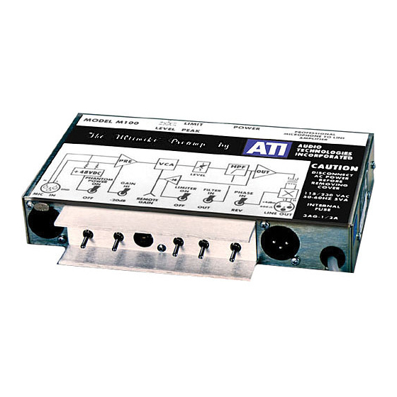
- Page 1 M100 MICROPHONE AMPLIFIER OPERATING AND MAINTENANCE MANUAL © Copyright 1997-2005, Audio Technologies Incorporated - Printed in USA Audio Technologies Inc. | 154 Cooper Road #902 | West Berlin, NJ 08091 | Voice 856-719-9900 | Fax 856-719-9903 | www. audio.com...
- Page 2 To allow you to install the M100 close to the mike when necessary in what may be a remote or poorly accessible location, we have designed the preamp to accept a very wide...
- Page 3 0 to –15 dB and does not interact with the limiter expect that both share the 24 dB total gain reduction range of the LDR. The remote gain control is DC operated and can operate a considerable distance from the M100 without pickup.
- Page 4 The M100 can mount to any flat surface with the included angle brackets, which should be mounted to opposite small faces if the M100 by the cover screws. The M100 can be rack mounted either singly or in pairs in only1 ¾” using accessory Front Panel Kit, P/N20273-501.
-
Page 5: Maintenance
A 10 Kohm linear potentiometer can be connected across a single conductor shielded cable with a standard RCA type phono plug at the M100 end. Connect the arm and one end of the pot together and to the shield, connect the other end of the pot to the center conductor. - Page 6 readjustment. Audio Technologies Inc. | 154 Cooper Road #902 | West Berlin, NJ 08091 | Voice 856-719-9900 | Fax 856-719-9903 | www. audio.com...
-
Page 7: Common Mode Rejection
If you cannot detect a good null your audio generator may well have more internal distortion at 20 Hz than even the untrimmed contribution of the M100, which is typically less than .25%. When properly set, using superior test equipment such as Amber or Audio Precision distortion measurements should be limited only by residual white to levels of .03% across the audible band. -
Page 8: Technical Specifications
TECHNICAL SPECIFICATIONS GAIN 54 dB nominal, adjustable 0 to 74 dB. NOMINAL POWER -50 dBm / 150 ohms available input power +4 dBm / 600 ohms output. PEAK LEVELS -32 dBu in, +22 dBm out. MAXIMUM INPUT 0 dBu- HI gain switch, +20 dBu- LO gain switch NOISE OUTPUT -70 dBm, 20 to 20,000 Hz measurement... - Page 9 COMPRESSOR THRESHOLD +14 dBm out +/- 1 dB. COMPRESSOR SLOPE 4 : 1 maximum. COMPRESSOR TIMING 100 mSec attack and recovery. COMPRESSOR RANGE 20 dB gain reduction minimum REMOTE GAIN TRIMMER 10 kohm linear external pot, user supplied DC control, 0 to –15 dB range. PHANTOM POWER +48 VDC at 4 ma.
Need help?
Do you have a question about the M100 and is the answer not in the manual?
Questions and answers