Advertisement
Advertisement
Table of Contents

Subscribe to Our Youtube Channel
Related Manuals for Daewoo FR-420N


Summary of Contents for Daewoo FR-420N
- Page 1 RFP341C001...
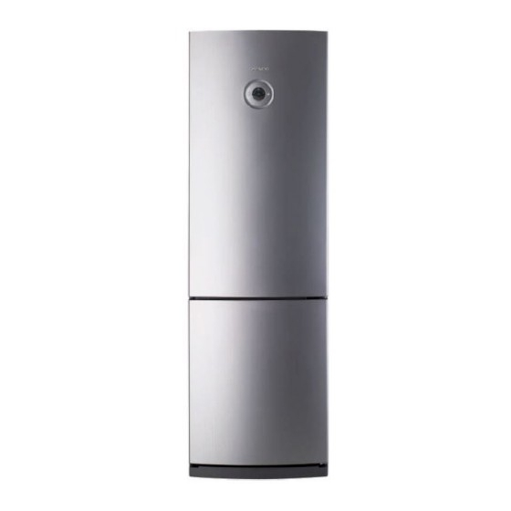
- Page 2 SPECIFICATIONS * is the Color 1. Model Information Buyer No. RF-420N* RN-420N* Factory No. RFP-341N….C RFP-341N….N Control Type FCP Button Control Total Gross Vol. Freezer (ISO 15502) Refrigerator Total Storage Vol. Freezer (ISO 15502) Refrigerator Width Diemension Depth Height 1898 1898 Refrigerant Type R-134a...
- Page 3 SPECIFICATIONS 2. Interior Parts - Features are model dependent ( Below is RF-420N model ) 1. Refrigerator Shelves 7. Feezer Case B 2. Lamp Window 8. Freezer Case C 3. Multi Duct 9. Dairy Pocket As 4. Basket Multiple (option ) 10.
-
Page 4: Specifications
SPECIFICATIONS 3. Machine (Compressor) Compartment View - Features are model dependent ( Below is RF-420N model ) Compressor 8. Compressor Absorber 1. Capacitor Run 9. Dryer As 2. Power Cord 10. Pipe Wire Condensor As 3. Suction Pipe As 11. Case vaporization As 4. - Page 5 SPECIFICATIONS 4. Refrigerant Cycle - Welding Point Copper Welding ( Ag 5%) 6 Point Silver Welding ( Ag 30%) 3 Point...
-
Page 6: Vegetable Compartment
SPECIFICATIONS 5. Temperature Diagram * Features are model dependent ( Below model is RF-420NT ) Refrigerator Dial Mode LOW ('1') : 3 ~ 6 degree MID ('3') : 0 ~ 3 degree HIGH ( '5' ) : -2 ~ 0 degree Vegetable compartment : 1 ~ 5 degree Freezer Mode... - Page 7 SPECIFICATIONS 6. Wiring Diagram 6-1. For RF-420N Models...
- Page 8 SPECIFICATIONS 6. Wiring Diagram 6-2. For RN-420N (R-600a) Models...
- Page 9 SPECIFICATIONS 6. Main PCB Circuit Diagram ( Only for RF-420N and RN-420N Models )
-
Page 10: Led Display
FUNCTIONS 1. DISPLAY INPUT CONTROL OBJECT PCB Control Panel Buttons PCB Control Panel LED Temperature adjustment button for refrigerator “Super Cool” button compartment. Reference Page No. LED DISPLAY FUNCTION OPERATION LED “3” on TEMP STEP “3” Push “TEMP” button 1 time. LED “4”... -
Page 11: Temperature Control Of Refrigerator Compartment
FUNCTIONS 2. Temperature Control of Refrigerator Compartment INPUT CONTROL OBJECT PCB Control Panel “TEMP” Buttons PCB Control Panel LED COMPRESSOR, FAN R-sensor A. “TEMP” Button 1. Temperature control of Refrigerator compartment 2. 5 step mode of successive temperature mode 3. Initial mode by power input: step “3” 4. - Page 12 FUNCTIONS 3. Defrost Mode INPUT CONTROL OBJECT Total COMP Work Time COMP Working Rate Defrost Mode Total Door Open Time / RT Conditions of Defrost Mode A. When total operation time of compressor becomes: 6, 8, 10, 12 hours. - any error mode-R1, D1, F3, C1, RT/S, Door SW error- happens. - or, running rate of COMP (per 2hrs of total operation time) is more than 80%.
- Page 13 FUNCTIONS 3. Defrost Mode INPUT CONTROL OBJECT Total COMP Work Time / COMP Working Rate Defrost Mode Total Door Open Time / RT Initial Defrost A. When initial power input or returning power failure. if the temperature at the Defrost Sensor is below 3.5 C, Defrost Mode starts. ( It prceeds from 'PRE-COOL' ), [ PRE-COOL - Heater On - Pause (10min) - Normal Operation ] B.
- Page 14 FUNCTIONS 4. Function of Low Ambient Temperature (RT) INPUT CONTROL OBJECT R-HTR COMP A. Condition of LOW RT - LOW RT Period : RT sensor below 19C - When the temperature of RT sensor is over 20C, the system comes to be “General Operation Mode”. - When the temp.
- Page 15 FUNCTIONS 7. Time Reduction INPUT CONTROL OBJECT ”FAST KEY” Buzzer A. HOW TO REDUCE - 1 min : Click FAST KEY one time on MAIN PCB. - 30 min : If you press FAST KEY continuously, you can reduce 30 minutes on each 2.5 seconds with buzzer.
-
Page 16: Control Of R-Sensor Off Point
FUNCTIONS 9. Control of R-sensor OFF Point INPUT CONTROL OBJECT Control Resistance of R sensor OFF Point ”J1” , “J2” On Main PCB A. LOW COOLING OPTION ( Weak Cooling ) - When the refrigeration of refrigerator is poor or weak though Fan and COMP are working continuously, the following actions are recommended for service. - Page 17 FUNCTIONS 9. Control of R-sensor OFF Point INPUT CONTROL OBJECT Input voltage of MICOM ”J3” & “R30” On Main PCB R-sensor ON/OFF Point B. Prevention OPTION of EXCESSIVE OR LOW COOLING. MICOM 26PIN OPTION 3 (P63) ; The input voltage of MICOM and R-Sensor ON/OFF point by changing J3 & R30. APPLICATION MICOM Compared to...
- Page 18 FUNCTIONS 9. Control of R-sensor OFF Point INPUT CONTROL OBJECT Input voltage of MICOM ”J4” & “R23” On Main PCB R-sensor ON/OFF Point C. Changing Difference between R-sensor “On” point and “Off” point. MICOM 27PIN OPTION 2 (P64) ; The input voltage of MICOM and R-Sensor ON/OFF DIFF. by changing J4 & R23. APPLICATION MICOM DIFFERENCE OF...
- Page 19 FUNCTIONS 10. Error Display INPUT CONTROL OBJECT PCB Control Panel Buttons / Door LED Lamp - ERROR DISPLAY - To confirm error happens or not, push S-COOL” button for continuously and “TEMP” button 5 times. - To stop the Error Display Set, push “TEMP” button 1 times, or wait 4 minutes. - After operations back to normal, the displays come to be reset.
- Page 20 FUNCTIONS 11. Function Key Summary Table MODE Action Button / Remark How to enter the Mode Temp + S-Cool button 5 times Forced Defrost Mode How to terminate After Mode ends ( about 1 hour ) Display '3', 'S-Cool' LED ON (In Error Mode) How to enter the Mode Temp button 30 times Pull Down Mode...
- Page 21 DISASSEMBLY 1. Front PCB Procedure Procedure Inuput a cutter sleeve between Window FCP and Panel F control. ( Be careful not to scratch the surface. ) Unscrew Panel F Control. Lift up the Window FCP. ( Input cutterr deeply to lift up easily.) Pull up the Panel and disconnect the wire connector.
- Page 22 DISASSEMBLY 2-2. RN-420N.. Models Procedure Procedure Remove top cover hinge screw with (+) driver. Remove the Door Switch from the cover hinge. Separate the Cover hinge by using driver. Disconnect door switch connector. Be careful not to scratch the cabniet surface. 3.
- Page 23 DISASSEMBLY 4. Freezer Louver As Procedure Procedure Unscrew the fixing screw to remove the Louver F As Remove 3 screws in order to disassemble Louver F As. Remove the Louver F As pulling the top side. When disassembling check the Knob position. L M H Disconnect Fan motor wire housing.
- Page 24 How to change Door opening Dirction (Reversable) Below process is for RN-420N (Refrigerant type : R-600a) models. Some parts are differ to RF-420N models. ( Hinge Cover, Door Switch, Wire Harness and Button Door Switch. ) When you change door opening direction ( RF-420N models ), please refer page 20 (Door switch Disassemlby) and below. Procedure Procedure Button...
- Page 25 How to change Door opening Dirction (Reversable) Procedure Procedure Screw the middle hinge to fix the Freezer Door. Connect the wire harness to door swtich. ( Washer should be up. ) ( Be careful the dircetion. ) Also assemble wire cover on the top plate. ( On the right Assemble Door and hing cover.
-
Page 26: Tools
How To Charge R-600a Refrigerant 1. Safety Warning ( R-600a Refrigerant Models Only, RN-420N.. ) his appliance contains a certain amount of isobutane refrigerant (R600a) a natural gas with high environmental compatibility that is, however, also combustible. When transporting and installing the appliance, care should be taken to ensure that no parts of the refrigerating circuit are damaged. - Page 27 How To Charge R-600a Refrigerant 3. Process Summary 1st Step. 2nd Step. 3th Step. R-600a ref. Removing Exchanging comp. discharging the remaning refrigerant & dryer / pipe welding - Connect the dis- - For removing of - Exchange Comp. and Dryer charging hose to remaning refrigerant., - Welding the Pipe...
- Page 28 How To Charge R-600a Refrigerant S VC process Image Details 1. And then, connect the vacuum pump to the outlet of discharging hose Remov ing the ※ Vacum pump should be placed at remaining ref. the outdoor where is able to clear air easily. ※...
- Page 29 How To Charge R-600a Refrigerant SVC process Image Details 1. Weld after inserting the coupling pipe to the compressor. Coupling pipe welding ※ Use the wet cloth for preventing the other part of machinery-room from damage. 1. Reassemble the valve ass'y with coupling pipe to clockwise.
-
Page 30: Leakage Test
How To Charge R-600a Refrigerant S VC process Image Details 1. Conect can adapter to the coupling pipe. 2. Charge the ref. with open lever slowly. Connecting of coupling pipe & adapta ※ Refrigerant should never leak in the room. 1. - Page 31 Cabinet Cabinet / Evaporator / Compressor Compartment Q'ty PART-CODE PART NAME SPEC. RF-430N RN-430N 3001416620 COVER M/PCB BOX AS COLOR DEPENDENT 30143G1060 PCB MAIN AS V-LAZER (RFP-340) 30143G1070 PCB MAIN AS V-LAZER (RFP-340 R600A) 3001412220 COVER CAB HRNS COLOR DEPENDENT 3018125601 SWITCH H/BAR DR AS COLOR DEPENDENT...
- Page 32 Refrigerator & Freezer Compartment Cabinet Q'ty PART-CODE PART NAME SPEC. RF-430N RN-430N SHELF R INSERT AS 3017847100 3010669900 BRACKET MULTI GPPS 3017847100 SHELF R INSERT AS 3001413300 COVER V/CASE AS COVER+KNOB CASE VEGETB GPPS 3011197500 3015513100 WINDOW R MIPS 3013603000 LAMP 240V,25W(BLUE) 3001413500...
- Page 33 Refrigerator & Freezer Door Compartment Cabinet Q'ty PART-CODE PART NAME SPEC. RF-430N RN-430N POCKET DAIRY AS RFP-341 3019056100 3011190800 CASE EGG TRAY GPPS 3019055900 POCKET BOTL GPPS 3012532100 GUIDE BOTL POKT POCKET JUMBO GPPS 3019055800 3000077800 RFP-341(WHITE) ASSY R DR 3000077820 RFP-341(SILVER) 3000077840...
Need help?
Do you have a question about the FR-420N and is the answer not in the manual?
Questions and answers