Table of Contents
Advertisement
TABLE OF CONTENTS
1 Safety Precautions----------------------------------------------- 2
2 Specifications ----------------------------------------------------- 3
3 Location of Controls and Components ------------------- 4
4 Operating Instructions------------------------------------------ 6
5 Test Mode ----------------------------------------------------------13
6 Troubleshooting Guide ----------------------------------------15
7 Disassembly and Assembly Instructions ---------------17
8 Wiring Connection Diagram ---------------------------------30
9 Exploded View and Replacement Parts List -----------32
Model No.
Chassis
Product Color White
Destination
PAGE
© Panasonic Corporation 2010 Unauthorized copy-
ing and distribution is a violation of law.
OrderNo.PTW1003508CE
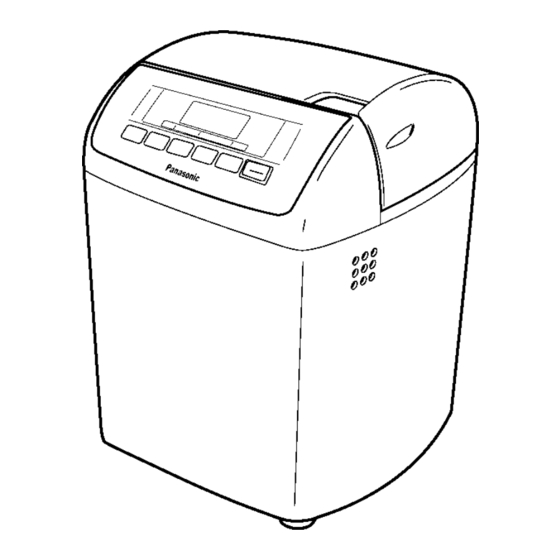
Automatic Bread Maker
SD-257WST
Australia
PAGE
Advertisement
Table of Contents
Troubleshooting

Related Manuals for Panasonic SD-257WST


Summary of Contents for Panasonic SD-257WST
- Page 1 5 Test Mode ----------------------------------------------------------13 6 Troubleshooting Guide ----------------------------------------15 7 Disassembly and Assembly Instructions ---------------17 8 Wiring Connection Diagram ---------------------------------30 9 Exploded View and Replacement Parts List -----------32 © Panasonic Corporation 2010 Unauthorized copy- ing and distribution is a violation of law.
-
Page 2: Safety Precautions
1 Safety Precautions... -
Page 3: Specifications
2 Specifications Power supply 230-240V -50 Hz Power consumed 505-550 W Capacity (Strong flour for a loaf) max.550g min.400g (Strong flour for a dough) max.600g min.250g (Yeast) max.8g min.0.75g Capacity of raisin nut dispenser max.150g dried fruit/nuts Timer Digital timer (up to 13 hours) Dimensions (H ×... -
Page 4: Location Of Controls And Components
3 Location of Controls and Components... -
Page 6: Operating Instructions
4 Operating Instructions... -
Page 13: Test Mode
5 Test Mode 5.1. Key operation and check mode Before trobleshooting, operate the checkmode in the following procedure. 5.1.1. Check mode 5.1.1.1. Electric power breakdown mode When an electric power breakdown is detected, all load of the Indication on LCD device goes off in this mode. - Page 14 5.1.1.2. Sensor disconnection mode When the disconnection of a sensor is detected, all load of the device goes off in this mode. Indication on LCD • "H01" is displayed on the LCD during the sensor disconnec- tion. ("H01" is brinking) 5.1.1.3.
-
Page 15: Troubleshooting Guide
6 Troubleshooting Guide Before troubleshooting, operate the main body test mode in the following procedure in order to check the P.C.Boards. 6.1. Main body test mode 6.1.1. Setting the main body initial test mode Operation procedure Judgement/Remedy 1. Insert the power cord plug into an electrical outlet. •... - Page 16 6.1.3. Solenoid/motor operation test (Volume.2) mode Operation procedure Judgement/Remedy 1. Press the "Timer" key. • Replace the solenoid and/or P.C.Board B if the solenoid Phenomena does not work. • LCD indication: It light up like the right figure. • Check and remedy the driving parts, i.e., pulley B, belt or •...
-
Page 17: Disassembly And Assembly Instructions
7 Disassembly and Assembly Instructions Important: • Refer to the tips on assembly, and carry out the disassembly procedure backward to assembly. • Remove the bread pan assy and kneading blade B unit before disassembling. 7.1. Dispenser cover assy 1. Remove the dispenser cover from the hinge part. 2. - Page 18 7.2. Top lid assy 1. Detach the hinge screw. 2. Slide the top lid assy and remove it from its hinge part.
- Page 19 3. Remove 3 screws from the inner lid. 4. Remove the inner lid with the ( - ) top screw driver wrenching into the chink between the top lid assy and the inner lid. * The inner lid is held with the top lid assy by 8 locks. 5.
- Page 20 7.3. Control panel unit 1. Remove 2 screws. 2. Unlock the control panel inner lid from the upper frame lock part while lifting the control panel unit, and while pushing 2 square holes with ( - ) top screw driver. 3.
- Page 21 7.4. Solenoid assy B 1. Remove the screw and detach the solenoid assy B, sole- noid fixing plate and spring A.
- Page 22 7.5. P.C.Board A 1. Remove 2 screws and detach P.C.B cover. 2. Disconnect the flat cable and lead wire from P.C.Board A. 3. Remove the P.C.Board A from the P.C.B cover.
- Page 23 7.6. Body and others 1. Remove 4 screws for rubber leg fixing, and detach the rubber legs. 2. Remove 2 screws and detach the cord support. 3. Remove the glass tape and disconnect the connector for the power cord assy. 4.
- Page 24 7.7. Upper frame 1. Remove 3 screws. 2. Remove the upper frame and the device body in order to disconnect the locks.
- Page 25 7.8. P.C.Board B 3. Remove 2 screws and detach P.C.B holder. 4. Remove the P.C.Board B assy from the P.C.B holder. 1. Remove the screw and detach the P.C.B holder lid. * The P.C.Board B assy is held to the P.C.B holder with 4 2.
- Page 26 7.9. Heat insulator and grand wire A assy 1. Remove the bind wires A of the lead wires. 2. Move the non-flammable tubes A and C and disconnect the 2 faston terminals from the heater. 3. Remove the screw and detach the heat insurator. 4.
- Page 27 7.10. Sensor assy 1. Remove the screw and hexagon nut and detach the sen- sor assy from the heater case unit. Tips on assembly • Insert the notched part of the sensor assy into the fixing square hole of heater case unit and screw the sensor assy to the heater case unit.
- Page 28 7.12. Heater case base assy and heater case unit 1. Remove the 4 screws and detach the heater case base assy. 2. Remove the heater case unit from the angle. Tips on assembly • Set the positioning marks across from each other on the heater case side and on heater case base side.
- Page 29 7.14. Motor assy 1. Remove 4 screws and detach the motor assy. 7.15. Bread pan 1. Turn the bread pan upside down and remove 3 screws. 2. Remove the packing. Tips on assembly • Set the positioning marks across from each other when assembling the mounting shaft assy and the bread pan.
-
Page 30: Wiring Connection Diagram
8 Wiring Connection Diagram 8.1. Schematic diagram... - Page 31 8.2. Basic wiring diagram...
-
Page 32: Exploded View And Replacement Parts List
9 Exploded View and Replacement Parts List 9.1. PARTS LOCATION... - Page 33 9.2. REPLACEMENT PARTS LIST Notes:Important safety notice • Components identified by mark have special characteristics important for safety. • " When replacing any of these components use only manufacturer's specified parts." MODEL No.SD-257-WST Australia Safety Ref. No. Part No. Part Name & Description Pcs/Set Remarks <PARTS LIST>...
- Page 34 Safety Ref. No. Part No. Part Name & Description Pcs/Set Remarks <SMALL STANDARDIZED METAL PARTS> XTB4+14BFC 4 x 14 Binding head tapping screw XTT4+10BFC 4 x 10 Truss head tapping screw XTB4+14BFJ 4 x 14 Binding head tapping screw XTB4+22BFJ 4 x 22 Binding head taptite screw XSS4+8UW 4 x 8 Flush head machine screw...
- Page 35 9.3. PACKING INSTRUCTION...
Need help?
Do you have a question about the SD-257WST and is the answer not in the manual?
Questions and answers