Table of Contents
Advertisement
UNVENTED (GAS LOG) ROOM HEATER
INSTALLATION AND OPERATING INSTRUCTIONS
Models HM2-MAN, HM2-T and HM2-MIL-18", 24" and 33" Burner Units
WARNING:
maintenance can cause property damage, personal injury or loss of life. Refer to
this manual for information. Installation and service must be performed by a
qualified installer, service agency or the gas supplier.
This is an unvented gas-fired heater. It uses air (oxygen) from the room
in which it is installed. Provisions for adequate combustion and
ventilation air must be provided. Refer to page 5 of these instructions.
This appliance is for supplemental heating only. It should not
be used as a primary heat source for a dwelling.
This heater is equipped with a PILOT LIGHT SAFETY SYSTEM designed to turn off the heater
if not enough fresh air is available.
DO NOT TAMPER WITH PILOT LIGHT SAFETY SYSTEM
WARNING:
may result causing property damage, personal injury or loss of life.
Do not store or use gasoline or other flammable vapors and liquids in the vicinity of this or any other
appliance.
WHAT TO DO IF YOU SMELL GAS
Do not try to light any appliance.
Do not touch any electrical switch; do not use any phone in your building.
Immediately call your gas supplier from a neighbor's phone. Follow the gas
supplier's instructions.
If you cannot reach your gas supplier, call the fire department.
Installation and service must be performed by a qualified installer, service agency or the gas supplier.
16-1010 (04/01)
with HM2-RO and HM2-SO Log Sets
Improper installation, adjustment, alteration, service or
If the information in this manual is not followed exactly, a fire or explosion
Advertisement
Table of Contents

Related Manuals for Heatmaster HM2-MAN


Summary of Contents for Heatmaster HM2-MAN
-
Page 1: Installation And Operating Instructions
UNVENTED (GAS LOG) ROOM HEATER INSTALLATION AND OPERATING INSTRUCTIONS Models HM2-MAN, HM2-T and HM2-MIL-18”, 24” and 33” Burner Units with HM2-RO and HM2-SO Log Sets WARNING: Improper installation, adjustment, alteration, service or maintenance can cause property damage, personal injury or loss of life. Refer to this manual for information. -
Page 2: Attention Installer
IMPORTANT: BEFORE BEGINNING INSTALLATION READ COMPLETE INSTRUCTIONS CAREFULLY. WARNING! When used without fresh air, heater may give off CARBON MONOXIDE, an odorless poisonous gas. DO NOT TAMPER WITH PILOT LIGHT SAFETY SYSTEM This heater is equipped with a PILOT LIGHT SAFETY SYSTEM designed to turn off the heater if not enough fresh air is available. - Page 3 WARNING: This appliance is for installation only in a solid-fuel burning fireplace or approved ventless firebox enclosure. Do not use this room heater if any part has been under water. Immediately call a qualified service technician to inspect the room heater and to replace any part of the control system and any gas control which has been under water.
- Page 4 Installation Clearances section of this brochure. If a hood is required to be installed on your fireplace due to mantle clearances, contact your dealer or HEATMASTER, INC. for availability of the hood. Any outside air ducts and/or ash dumps in the fireplace shall be...
- Page 5 COMBUSTION AND VENTILATION PROVISIONS WARNING: This heater shall not be installed in a confined space or unusually tight construction unless provisions are provided for adequate combustion and ventilation air. Confined Space and Unconfined Space The National Fuel Gas Code, ANSI Z223.1 defines a confined space as a space whose volume is less than 50 cubic feet per 1,000 Btu per hour (4.8m³...
-
Page 6: Installation Clearances
INSTALLATION CLEARANCES To ensure a safe installation in a masonry or approved factory built fireplace, the following instructions must be carefully followed. A) Minimum clearance from the side of the fireplace opening to any combustible wall should not be less than 15 inches. B) Minimum clearance from the top of the fireplace opening to any combustible ceiling should not be... - Page 7 INSTALLATION INSTRUCTIONS WHEN INSTALLING AS A VENT FREE APPLIANCE The installation of this appliance must conform with local codes or, in the absence of local codes with the National Fuel Gas Code, ANSI Z223.1. NOTE: Before the unit is connected to any gas line, check the name plate on the unit for the proper gas type you will be using.
-
Page 8: Assembly Instructions
ASSEMBLY INSTRUCTIONS 1. Remove grate/burner assembly from the box and place in the center of the fireplace. 2. Connect the gas line to the appliance regulator located under the grate. NOTE: The manual and thermostat valve units will have this appliance regulator. The millivolt valve will not have this regulator. -
Page 9: Operating Instructions
If a wall switch, thermostat or remote control has been purchased, you must follow installation and operating instructions on pages 11and 12 of this instruction manual. HM2-MAN 18,24 & 33 LP and Natural Gas (See FIG. 1) 1. Notice the white marker line between the igniter button and the control knob. This white marker line is the line-up mark for the control knob. - Page 10 7. Allow the unit to operate at the highest setting until the room temperature reaches your comfort level. 8. Turn the control knob clockwise until the flame goes out. This sets the control valve to operate in this temperature range. 9.
-
Page 11: Wall Switch
INSTALLATION INSTRUCTIONS for HM2 MIL 18,24 & 33 ACCESSORIES (Wall Switch, Thermostat, Remote Control) WALL SWITCH It is suggested by the manufacturer that a qualified individual complete this installation. Your HM2 MIL Series log set is shipped from the factory set up to operate without the use of any of the accessories. -
Page 12: Thermostat Remote Control
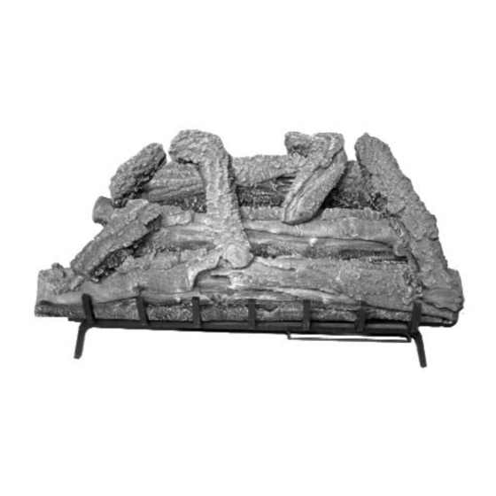
2. Follow the instructions supplied with the Thermostat Remote Control. This is a millivolt gas valve. It is recommended by Heatmaster, Inc. that all precautions are followed exactly. (In the instructions supplied with the remote control, there are instructions about a crackling sound system. This is an optional system and is not available from Heatmaster, Inc.) - Page 13 LOG PLACEMENT PHOTOS (RO SERIES) HM2-RO-18 Front View HM2-RO-18 Side View HM2-RO-24 Front View HM2-RO-24 Side View HM2-RO-33 Front View HM2-RO-33 Side View WARNING: Failure to position the parts in accordance with these diagrams or failure to use only the parts specifically approved with the heater may result in property damage or personal injury.
- Page 14 LOG PLACEMENT PHOTOS (SO SERIES) HM2-SO-18 Front View HM2-SO-18 Side View HM2-SO-24 Front View HM2-SO-24 Side View HM2-SO-33 Front View HM2-SO-33 Side View WARNING: Failure to position the parts in accordance with these diagrams or failure to use only the parts specifically approved with the heater may result in property damage or personal injury.
-
Page 15: For Your Safety Read Before Lighting
FOR YOUR SAFETY READ BEFORE LIGHTING WARNING: If you do not follow these instructions exactly, a fire or explosion may result causing property damage, personal injury or loss of life. A. This appliance has a pilot which must be lighted by hand. When lighting the pilot, follow these instructions exactly. This appliance is equipped with a push button piezo ignition device which can be used to light the pilot. - Page 16 FOR YOUR SAFETY READ BEFORE LIGHTING WARNING: If you do not follow these instructions exactly, a fire or explosion may result causing property damage, personal injury or loss of life. A. This appliance has a pilot which must be lighted by hand. When lighting the pilot, follow these instructions exactly. This appliance is equipped with a push button piezo ignition device which can be used to light the pilot.
-
Page 17: Cleaning And Maintenance Instructions
CLEANING AND MAINTENANCE INSTRUCTIONS ALWAYS REMEMBER: 1. Do not operate this appliance without the fireplace screen closed. 2. Do not place any combustible material near the appliance. 3. Do not place any paper, trash or other material on the log set or in the heater. 4. - Page 18 PROPANE GAS NATURAL GAS MANUAL AND THERMOSTATIC VALVES NATURAL GAS PROPANE GAS MILLIVOLT VALVES 18” Log Set 24” Log Set 33” Log Set...
-
Page 19: Installation Instructions
INSTALLATION INSTRUCTIONS WHEN INSTALLING AS A VENTED DECORATIVE APPLIANCE When installing as a vented appliance, the following statements and charts must be followed. Thermostat models can not be installed as a vented appliance under ANSI Z21.60-CGA 2.26- M96T standard (i.e. HM2-Tstat-24 and HM2-Tstat-33). This appliance must be installed only in a solid-fuel burning fireplace with a working flue, and constructed of noncombustible material. -
Page 20: Factory Built Fireplaces
TABLE 1A FACTORY BUILT FIREPLACES Free opening area of chimney damper for venting combustion products from decorative appliances for installation in solid fuel burning fireplaces. MINIMUM PERMANENT FREE OPENING IN SQUARE INCHES Chimney 18” Log Set 18” Log Set 24” Log Set 24”... - Page 21 Log # 274 Center Bottom Log Log # 434 Center Right Log Parts may be ordered directly from: HEATMASTER, INC. 3625 Benson Road, P.O. Box 1717 Angier, NC 27501 (919) 639-4568 When ordering, please include complete part number, part name and description.
-
Page 22: Parts Diagram
PARTS DIAGRAM... -
Page 23: Parts List
16-1130 Piezo Wire 12" 11-1441 3/16" Loxit Nut & Sleeve Parts may be ordered directly from: HEATMASTER, INC. 3625 Benson Road, P.O. Box 1717 Angier, NC 27501 (919) 639-4568 When ordering, please include complete part number, part name and description. -
Page 24: Limited Warranty
All refractory cement logs manufactured by HEATMASTER, Inc. have a lifetime warranty against breakage due to heat to the original owner in the original installation. All other logs supplied from HEATMASTER, Inc. have a 2 year warranty against breakage due to heat to the original owner in the original installation.
Need help?
Do you have a question about the HM2-MAN and is the answer not in the manual?
Questions and answers
Pilot is lit but grates won't ignite
If the grates (burner) on the Heatmaster HM2-MAN won’t ignite when the pilot is lit, possible causes include:
1. The manual shutoff valve is not fully open.
2. The thermocouple is loose or damaged, preventing proper operation.
3. The pilot flame is not properly touching the thermocouple, causing it to cool and shut off the gas.
4. There may be low gas pressure or a clogged pilot.
5. The control valve may be damaged.
These issues can prevent the burner from lighting even if the pilot stays lit.
This answer is automatically generated