
Subscribe to Our Youtube Channel
Related Manuals for GE ZIB240P


Summary of Contents for GE ZIB240P
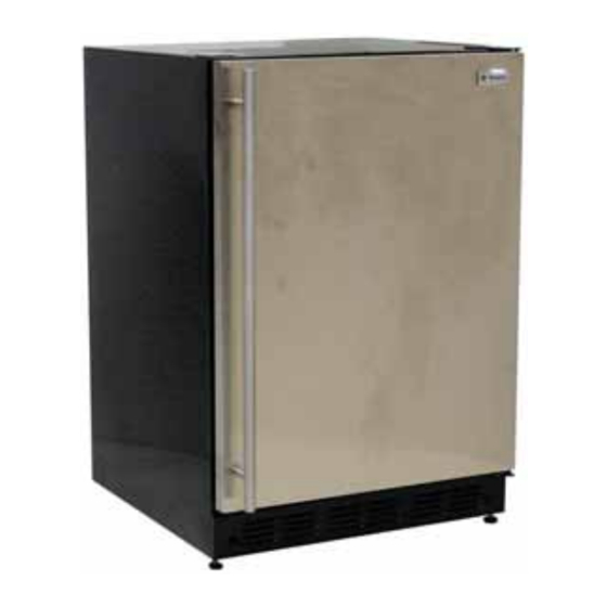
- Page 1 GE Consumer & Industrial TECHNICAL SERVICE GUIDE Bar Refrigerator with Icemaker MODEL SERIES: ZIB240P PUB # 31-9124 11/04...
- Page 2 If grounding wires, screws, straps, clips, nuts, or washers used to complete a path to ground are removed for service, they must be returned to their original position and properly fastened. GE Consumer & Industrial Technical Service Guide Copyright © 2004 All rights reserved.
-
Page 3: Table Of Contents
Table of Contents Child Control Lockout .......................7 Cleaning the Outside .......................7 Components ........................8 Component Locator Views ....................20 Compressor ........................19 Condenser Fan .......................18 Control Panel ........................9 Control Features ......................7 Damper Assembly ......................15 Defrost Heater and Fill Tube Heater ................17 Diagnostics and Service Information ................21 Evaporator Compartment ....................16 Evaporator Cover ......................13 Evaporator Fan ........................13... -
Page 4: Introduction
Introduction This manual covers service information for the Bar Refrigerator with Icemaker. The temperature setting for the refrigerator is factory set at 38°F. The ambient temperature range is from 70°F to 90°F. The leveling legs are factory installed. The evaporator is located behind the evaporator cover of the freezer compartment, and is not serviceable. -
Page 5: Nomenclature
Nomenclature Model Number Z D B I 2 4 0 P A S S Monogram Exterior Color Product BS = Black Case/ Stainless Door Installation SS = Stainless Steel D = Built-In or Freestanding II = Custom Panel I = Built-In Model Year Designator Confi... -
Page 6: Technical Data
Technical Data IMPORTANT SAFETY NOTICE DISCONNECT POWER CORD BEFORE SERVICING This information is intended for use by individuals IMPORTANT - RECONNECT ALL GROUNDING DEVICES possessing adequate backgrounds of electrical, All parts of this appliance capable of conducting electronic and mechanical experience. Any electrical current are grounded. -
Page 7: Child Control Lockout
COLDER steel cleaner, such as Stainless Steel Magic™. set temperature. After 5 seconds, the display will Stainless Steel Magic™ is available through GE return to the actual temperature. Allow 12 to 24 Parts and Accessories, 800.626.2002 or GE hours for the refrigerator to reach the temperature Appliances.com. -
Page 8: Components
Components Icemaker Full Extension Drawer The icemaker will produce seven cubes per To remove the full extension drawer, pull the cycle - approximately 100 to 130 cubes per day drawer out to the STOP position. Push the tab on (approximately 4.8 lbs). Ice rate is dependant the right rack guide down while pulling the tab on on freezer compartment temperature, room the left rack guide up, and pull the drawer out. -
Page 9: Control Panel
Control Panel Power Supply Board The control panel is held in place by 2 Phillips- The power supply board is housed in a sliding head screws. tray above the machine compartment. The tray is held in place by 2 Phillips-head screws. Caution: When reinstalling the control panel, make sure control panel wires are routed properly to avoid pinching. - Page 10 Power Supply Board Replacement 6. Verify that the replacement board has been jumpered correctly by comparing the model The replacement power supply board comes number displayed on the control panel with with 4 jumpers. The jumpers must be moved to the table of model numbers below.
-
Page 11: Thermistors
Resistance Checks Thermistors for appropriate Thermistor Resistance Chart Run diagnostic mode 07 to test the circuit resistance values. between the power supply board and thermistors. See Diagnostics and Service Information Freezer Compartment Thermistor - K9 on the The refrigerator has 3 serviceable thermistors: power supply board (pin 1 and pin 2). -
Page 12: Freezer Compartment
8. Pull the freezer compartment forward as Freezer Compartment shown until clear. To remove the freezer compartment: 1. Remove ice storage bin, drawer, and shelves. 2. Remove the freezer thermistor cover. Unclip the freezer thermistor from the holding bracket. 3. Remove the control panel. 4. -
Page 13: Evaporator Cover
4. Carefully pull the evaporator cover out from Evaporator Cover the refrigerator compartment as shown below. The evaporator cover must be removed to access Caution: When removing the evaporator cover, the evaporator fan, damper assembly, evaporator DO NOT bend it from side to side, the foam air components, and fi... - Page 14 To remove the evaporator fan: 3. The evaporator fan is held in place by 4 fl exible corner supports. The evaporator fan 1. Remove the evaporator cover. (See and corner supports can be removed from the Evaporator Cover. evaporator cover as one unit. 2.
-
Page 15: Damper Assembly
To remove the damper assembly: Damper Assembly 1. Remove the evaporator cover. (See Run diagnostic mode 10 to test the damper. ( Evaporator Cover. Diagnostics and Service Information 2. Remove the fan housing. (See Evaporator The damper assembly regulates the cool air Fan. -
Page 16: Evaporator Compartment
4. Tilt the damper assembly as shown, then Evaporator Compartment remove it from the fan housing. The evaporator compartment has 4 serviceable components: • Fill Tube Heater • Defrost Heater • Fuse Link • Evaporator Thermistor The evaporator is not serviceable. Note: The fuse link opens at 183°F and cannot be reset. -
Page 17: Defrost Heater And Fill Tube Heater
To remove the defrost heater: Defrost Heater and Fill Tube Heater 1. Disconnect the defrost heater at the plug-in Run diagnostic mode 14 to test the defrost cycle. connector. See Diagnostics and Service Information The termination temperature for the defrost cycle is 45°F at the evaporator thermistor. -
Page 18: Condenser Fan
To remove the condenser fan motor and Condenser Fan shroud: Run diagnostic mode 12 to test the circuit The condenser fan motor and shroud assembly between the power supply board, compressor, can be removed as one unit. and the condenser fan. ( See Diagnostics and Service Information 1. -
Page 19: Water Valve
Compressor Water Valve Run diagnostic mode 12 to test the circuit The water valve is located on the right side of the between the power supply board, compressor, machine compartment in front of the condenser. It and the condenser fan. ( is attached by a single 7-mm hex-nut. -
Page 20: Component Locator Views
Component Locator Views Machine Compartment Power Supply Board Condensate Pan Water Valve Compressor Drier Run Capacitor Junction Box Condenser Condenser Fan Note: The condensate pan is mounted to the top of the compressor. A bead of silicone foam has been applied to prevent noise caused by vibration. This bead can be broken by use of a putty knife or screwdriver. -
Page 21: Diagnostics And Service Information
Diagnostics and Service Information NOTE: Indicates keypad used only on some models. To Enter Service Mode: To Exit Service Mode: Press keypads A, B and D simultaneously for 5 seconds. Press keypads A, B and D simultaneously for 5 seconds or enter Service Mode Option 1 6. - Page 22 Diagnostic Diagnostics Description Mode Checks each thermistor. The following is displayed for 1 second and then the instantaneous temperature for 5 minutes or until any other key is pressed: "FF" = Fresh- Food "EP" = Evaporator "IC" = Icemaker. Note: If no Sensor System Test Icemaker, a "- -"...
- Page 23 Load Chart Device Model VAC 120 120 120 120 120 120 Bar Unit – 23 –...
-
Page 24: Icemaker
Schematic WARNING: Disconnect electrical power before servicing. DC SIDE POWER SUPPLY BOARD AC SIDE BROWN BLACK LINE 120V FF NTC BROWN or BLUE WHITE WHITE NEUTRAL POWER BLUE or BROWN GREEN/YELLOW CORD EVAP BLUE COMP BLACK GREY BLUE WHITE +12V COND. -
Page 25: Warranty
Warranty WHAT IS FULL ONE-YEAR WARRANTY For one year from date of original purchase, we will provide, free of charge, parts and service labor COVERED in your home to repair or replace any part that fails because of a manufacturing defect. From the Date FULL FIVE-YEAR WARRANTY For five years from date of original purchase, we will provide, free of charge, parts and service labor...
Need help?
Do you have a question about the ZIB240P and is the answer not in the manual?
Questions and answers