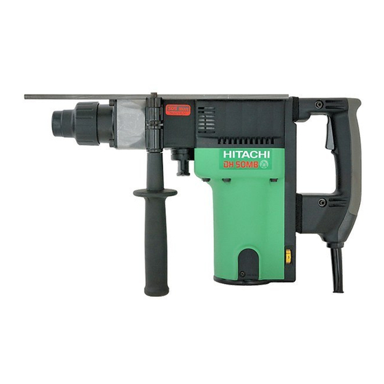
Hitachi DH 50MB Technical Data And Service Manual
Hammer drill
Hide thumbs
Also See for DH 50MB:
- Instruction manual (68 pages) ,
- Handling instructions manual (63 pages) ,
- Technical data and service manual (38 pages)

Related Manuals for Hitachi DH 50MB


Summary of Contents for Hitachi DH 50MB
- Page 1 MODEL DH 50MB POWER TOOLS TECHNICAL DATA HAMMER DRILL DH 50MB SERVICE MANUAL LIST No. E455 Feb. 2000 SPECIFICATIONS AND PARTS ARE SUBJECT TO CHANGE FOR IMPROVEMENT...
-
Page 2: Table Of Contents
Notice for use Specifications and parts are subject to change for improvement. Refer to Hitachi Power Tool Technical News for further information. CONTENTS [ Business Section ] Page 1. PRODUCT NAME • • • • • • • • • • • • • • • • • • • • • • • • • • • • • • • • • • • • • • • • • • • • • • • • • • • • • • • • • • • • • • • • • • • • • • • • • • • • • • • • • • • • • • • • • • • • • • • • • • • • • • • • • • • • • • • • • • • • • • • •... -
Page 3: Product Name
The market demand for 50 mm (2") class hammer drills is quickly changing from spline or hexagon bit shank types to a SDS-MAX bit shank type, especially in the European market. The new Model DH 50MB, which features the SDS-MAX bit shank, has been developed to meet that market demand. -
Page 4: Selling Points
4. SELLING POINTS Compact and lightweight: Overall length 495 mm (19-1/2"), Weight 9.8 kg (21.6 lbs.) : Overall length 595 mm (23-1/2"), Weight 10.8 kg (23.8 lbs.) : Overall length 610 mm (24-1/32"), Weight 10.0 kg (22.0 lbs.) Vibration-isolating handle reduces operator fatigue Faster drilling speed (About 1.8 times faster than the Model DH 40MA) -
Page 5: Selling Point Descriptions
4-1-1. Dial type, constant speed electronic control with stepless variable-speed The Model DH 50MB contains and electronic control circuit which allows the number of revolutions and the number of strikes to be stepless adjustable from levels 1 to 5 on the dial. The number of revolutions and the number of strikes are within the range of values in the graph shown below, due to variations of products. - Page 6 4-1-2. Faster drilling speed The drilling speed is 1.8 times faster than that of the Model DH 40MA, as the Model DH 50MB has greater striking energy owing to the optimized design of the rotation speed, striking frequency and the weight of striker.
-
Page 7: Specifications
5. SPECIFICATIONS 5-1. Specifications Drill bit (max. diameter); 50 mm (2"), Core bit (max. diameter); 160 mm (6-1/4") Capacity Power Source AC single phase 50 Hz or 60 Hz Voltage (V) Voltage, current and Current (A) 13.4 12.8 11.6 power input Power input (W) 1400 120 - - - 250 /min. -
Page 8: Optional Accessories
5-2. Optional Accessories 1. Drilling work for through-holes (rotation + hammering) (1) Drill bit (SDS max shank) Overall length Outer diameter Overall length Outer diameter Code No. Code No. (mm) (mm) (mm) (mm) 16 (5/8") 340 (13-3/8") 16 (5/8") 540 (21-1/4") 313448 313456 19 (3/4") - Page 9 SDS-plus shank bit adapter (1) Drill bit (SDS-plus shank) (2) SDS-plus shank bit adapter Code No. 313465 3. Boring work for large-diameter holes (rotation + hammering) (1) Guide plate (2) Center pin (3) Core bit (4) Core bit shank (1) Guide plate Core bits with outer diameter of 32, 35, 38, 45, 50, 54, 60, 64, 70, 75, 79, 94, 100, 105, 120, 150 mm (1-1/4", 1-3/8", 1-1/2", 1-3/4", 2", 2-1/8", 2-3/8", 2-1/2", 2-3/4", 2-15/16", 3-1/8", 3-11/16", 3-15/16", 4-1/8", 4-3/4", 6") [Guide plate is not used with core bits with outer diameter of 25 mm (1") and 29 mm (1-1/8")]...
- Page 10 4. Hole drilling For drilling steel and wood • • • • • • (2) Chuck adapter (1) 13 mm (1/2") drill chuck (13VLA) (3) Chuck wrench (1) 13 mm (1/2") drill chuck (13VLA) (2) Chuck adapter (3) Chuck wrench Code No.
- Page 11 8. Cutting and stripping (asphalt cutting, etc.) (hammering) (1) Cutter Overall length Width Code No. 50 mm (2") 400 mm (15-3/4") 313475 9. Digging (substitute pick-ax) (hammering) (1) Scoop Overall length Code No. 400 mm (15-3/4") 313476 10. Surface roughing work (hammering) (1) Bushing tool (2) Shank Overall length...
-
Page 12: Comparisons With Similar Products
Note: Code numbers listed above are subject to change without notice. Please refer to periodic Technical News Bulletins for updates. 6. COMPARISONS WITH SIMILAR PRODUCTS 6-1. Specification Comparisons Maker, Model HITACHI Item DH 50MB Drill bit dia. (mm) 50 (2") 52 (2") 37 (1-7/16") Capacity Core bit dia. (mm) 160 (6-1/4") -
Page 13: Drilling Speed Comparisons
Drilling speed varies considerably depending on the work conditions. Use the factory test results shown in Fig. 4 as a reference, for comparison purposes only. Fig. 4 Drilling speed (mm/min.) Drill bit dia. Maker Model (mm) HITACHI DH 50MB φ 16 HITACHI DH 50MB φ 19 HITACHI DH 50MB φ 22 HITACHI DH 50MB φ... -
Page 14: Chiseling Performance
Fig. 5 for comparison purposes only. Demolished amount (kg/30 min.) Voltage Maker Model supply HITACHI DH 50MB 230 V Fig.5 [Test conditions] Orientation : Downward chiseling Test material : Concrete panel with a compression strength of 2,919 N/cm... -
Page 15: Precautions In Sales Promotion
7. PRECAUTIONS IN SALES PROMOTION In the interest of promoting the safest and most efficient use of the Model DH 50MB Hammer Drill by all of our customers, it is very important that at the time of sales the salesperson carefully ensures that the buyer seriously recognizes the importance of the contents of the Handling Instructions, and fully understands the meaning of the precautions listed on the Caution Plate attached to each tool. -
Page 16: References
8. REFERENCES 8-1. Grease Replacement Procedures The electro-pneumatic hammering section and gear change section each use different kinds of grease. It is not necessary to replenish the grease unless the tool is disassembled for repair or there is a grease leakage due to a damaged seal. -
Page 17: Structure Of The Dh 50Mb Hammer Drill
Rotation transmission is described below with reference to Fig. 6. The gear arrangement of the Model DH 50MB has the armature shaft positioned between the crank shaft and bevel pinion shaft. Rotation of the armature shaft is transmitted to the second gear through the first gear of the crank shaft and the second pinion. - Page 18 Switching between "Drill + Hammering", "Neutral" and "Hammering only" The shanks of the SDS max type working tools are all Lock sleeve Bevel gear Clutch of the same shape for drill bits, bull points for chiseling and chipping and cold chisels. When chiseling and chipping with this hammer drill, it is necessary to stop the drilling motion and choose the "Hammering only"...
- Page 19 Mechanism to prevent idle hammering The arrangement against idle hammering of this hammer drill is about the same as for the DH 40MA/MB in which, when the drill bit or bull point is no longer pressed against the concrete or similar material, the second hammer moves to a position shown in Fig.
- Page 20 Drill bit As illustrated in Fig. 12, the tool holder is designed to accept SDS max shank bits so that torque transmission to the drill bit is accomplished with three key rails formed on the tool holder, with two needle rollers provided to prevent the drill bit from slipping out.
- Page 21 Tool holder The tool holder is described below with reference to Fig. 13. The drill bit inlet is covered with a front cap (rubber) to prevent entry of cutting chips. Two needle rollers fit into the round groove of the drill bit to prevent it from slipping out of the tool holder, while the three key rails provide positive torque transmission to the drill bit.
- Page 22 Wiring connections The wiring connections are described below with reference to Fig. 14. The Model DH 50MB uses a plug-in module type wiring system consisting of plug (A) ass'y and plug (B) ass'y. The internal wires (2 and 3) of the control circuit ass'y and the internal wires from the stator, and the internal wire (5) of the control circuit ass'y and the internal wire from the piece ass'y, are press-connected by crimp-on connectors.
- Page 23 Handle and side handle The handle section is of a two-layer structure consisting of a molded plastic base reinforced with glassfiber and a soft plastic layer molded together on the base. The side handle is also constructed of two layers consisting of a reinforced plastic base molded together with steel nut and soft plastic surrounding the base.
- Page 24 Indication lamp for carbon brush replacement The indication lamp for carbon brush replacement is described below with reference to Fig. 16. As the carbon brush wears, the guide piece mounted to the carbon brush moves toward the commutator. When the guide piece contacts the piece ass'y, the indication lamp will light up in red as the switch is turned on.
-
Page 25: Precautions In Disassembly And Reassembly
9. PRECAUTIONS IN DISASSEMBLY AND REASSEMBLY The [Bold] numbers in the descriptions below correspond to the item numbers in the Parts List and exploded assembly diagram. 9-1. Disassembly (1) Piston and striker Remove the four Nylock Bolts (W/Flange) M5 x 16 [31] at the Crank Case Cover Ass'y [33] and remove the latter. -
Page 26: Reassembly
9-2. Reassembly Perform reassembly in the reverse order of disassembly while observing the given precautions and taking care of the following points. (1) Lubrication Apply special grease (for hammer and hammer drill) to the following portions. Inner circumference of the Connecting Rod Ass'y [76] Two O-Rings [73] attached to the Striker [72] and Piston [75] Inner lip portion of the Oil Seals [10] and [92] Fill 30 g of special grease in the Cylinder Case [58] and 75 g of special grease in the Crank Case [35] of the... - Page 27 (3) Slip clutch ass'y Press-fit the Ball Bearing 6202 [18] into the Bevel Pinion [16] and insert the Washer [19] and then Washer (A) [20] into the Bevel Pinion. After mounting the Feather Key 3 x 3 x 8 [17] in the Bevel Pinion, press-fit the Gear Holder [21] into the Bevel Pinion.
- Page 28 (Caution) The factory-installed carbon brushes are not identical to each other as shown in Fig. 21. Pay attention to their difference when reassembling after inspection. There is no problem when replacing them with a pair of carbon brushes supplied as service parts (No. 77) because both parts are the same type (guide piece provided). Handle Housing Carbon brush...
-
Page 29: Screw Locking Agent Tb1401
9-3. Screw Locking Agent TB1401 Apply screw locking agent ThreeBond TB1401 to all of the M5 hexagon socket head bolts (except for M8 for front cover mounting and M6 hexagon socket head bolts for cylinder case mounting, which are special bolts to be treated as service parts). -
Page 30: Wiring Diagrams
9-5. Wiring Diagrams For products without noise suppressor Stator Switch Control Armature circuit ass'y Plug Connector For products with noise suppressor Switch Stator Noise suppressor Control circuit Armature ass'y Plug Pillar terminal Fig. 22 9-6. Insulation Test On completion of disassembly and repair, measure the insulation resistance and dielectric strength. Insulation resistance : 7 MΩ... -
Page 31: Standard Repair Time (Unit) Schedules
10. STANDARD REPAIR TIME (UNIT) SCHEDULES Variable 60 min. MODEL Fixed Work Flow DH 50MB Housing Ass'y Handle Cover Seal Packing Stator Ass'y Switch (C) Gear Cover Cord Needle Bearing Cord Armor Tail Cover Armature Ass'y Ball Bearing Ball Bearing... -
Page 32: Assembly Diagram For Dh 50Mb
Assembly Diagram for DH 50MB --- 30 ---... - Page 33 PARTS DH 50MB ITEM CODE NO. DESCRIPTION REMARKS USED 313-415 FRONT CAP 318-608 GRIP 318-590 STOPPER RING 313-413 NEEDLE HOLDER 313-419 RETAINER SPRING 318-589 SPRING HOLDER 880-810 NYLOCK HEX. SOCKET HD. BOLT M8X25 318-587 FRONT COVER 878-863 O-RING (S-70) 318-588...
- Page 34 DH 50MB PARTS ITEM CODE NO. DESCRIPTION REMARKS USED 318-580 RETAINER SLEEVE 986-104 O-RING 318-564 SECOND HAMMER 318-565 DAMPER WASHER 318-566 DAMPER 318-567 DAMPER HOLDER 318-568 CYLINDER CASE 318-451 NYLOCK BOLT (W/FLANGE) M6X35 318-560 NEEDLE BEARING 981-973 CYLINDER WASHER 985-779...
- Page 35 DH 50MB PARTS ITEM CODE NO. DESCRIPTION REMARKS USED 340-463C STATOR ASS'Y 110V-115V INCLUD.101 340-463D STATOR ASS'Y 120V-127V INCLUD.101 340-463E STATOR ASS'Y 220V-230V INCLUD.101 340-463F STATOR ASS'Y 240V INCLUD.101 340-463G STATOR ASS'Y 115V INCLID.101 FOR USA,CAN 958-032 BRUSH TERMINAL 318-607 HOUSING ASS'Y INCLUD.109,110,115,116...
- Page 36 DH 50MB PARTS ITEM CODE NO. DESCRIPTION REMARKS USED 313-092 PLUG (A) FOR USA,CAN 313-142 PLUG (A) 959-141 CONNECTOR 50092 (10 PCS.) FOR AUS 318-648 PLUG (B) 318-600 PLUG (B) FOR AUS 318-649 PLUG (B) FOR USA,CAN 938-307 PILLAR TERMINAL...
-
Page 37: Standard Accessories
DH 50MB STANDARD ACCESSORIES ITEM CODE NO. DESCRIPTION REMARKS USED 318-646 CASE (PLASTIC) 981-840 GREASE (A) FOR HAMMER.HAMMER DRILL (30G) 944-458 HEX. BAR WRENCH 4MM 944-459 HEX. BAR WRENCH 5MM 872-422 HEX. BAR WRENCH 6MM OPTIONAL ACCESSORIES ITEM CODE NO. - Page 38 DH 50MB OPTIONAL ACCESSORIES ITEM CODE NO. DESCRIPTION REMARKS USED 959-709 CORE BIT 75MM INCLUD.660 955-157 CORE BIT 79MM INCLUD.661 956-004 CORE BIT 94MM INCLUD.662 959-710 CORE BIT 100MM INCLUD.663 955-159 CORE BIT 105MM INCLUD.664 956-006 CORE BIT 120MM INCLUD.665...
Need help?
Do you have a question about the DH 50MB and is the answer not in the manual?
Questions and answers