Advertisement
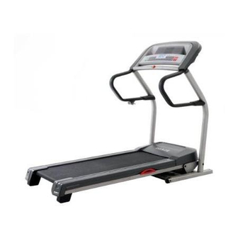
Model No. IMTL49105.0
Serial No.
USER'S MANUAL
Serial Number
Decal
QUESTIONS?
As a manufacturer, we are com-
mitted to providing complete
customer satisfaction. If you
have questions, or if parts are
damaged or missing, PLEASE
CONTACT OUR CUSTOMER
SERVICE DEPARTMENT
DIRECTLY.
CALL TOLL-FREE:
1-800-753-4645
Mon.–Fri., 6 a.m.–6 p.m. MST
ON THE WEB:
www.iconservice.com
CAUTION
Visit our website at
Read all precautions and instruc-
tions in this manual before using
www.imagefitness.com
this equipment. Save this manual
new products, prizes,
for future reference.
fitness tips, and much more!
Advertisement
Table of Contents

Subscribe to Our Youtube Channel
Related Manuals for Image IMTL49105.0


Summary of Contents for Image IMTL49105.0
- Page 1 Model No. IMTL49105.0 Serial No. USER'S MANUAL Serial Number Decal QUESTIONS? As a manufacturer, we are com- mitted to providing complete customer satisfaction. If you have questions, or if parts are damaged or missing, PLEASE CONTACT OUR CUSTOMER SERVICE DEPARTMENT DIRECTLY.
-
Page 2: Table Of Contents
HOW TO FOLD AND MOVE THE TREADMILL ........ -
Page 3: Important Precautions
11. Use only a single-outlet surge suppressor that meets all of the specifications described on page 11. To purchase a surge suppressor, see your local IMAGE dealer or call the toll-free telephone number on the front cover of this manual and order part number 146148, or see your local electronics store. - Page 4 SAVE THESE INSTRUCTIONS The decals shown here have been placed on the treadmill. If a decal is missing, or if it is not legible, call the toll-free telephone number on the front cover of this manual and order a free replacement decal.
-
Page 5: Before You Begin
17.0 R tread- number and serial number before calling. The model number of the treadmill is IMTL49105.0. The serial number can be found on a decal attached to the tread- mill (see the front cover of this manual for the location). -
Page 6: Assembly
During shipping, a small amount of lubricant may be transferred to the top of the walking belt or the shipping carton. This is a normal condition and does not affect treadmill perfor- mance. If there is lubricant on top of the walking belt, simply wipe off the lubricant with a soft cloth and a mild, non-abrasive cleaner. - Page 7 2. Orient the Right Upright (36) so the square hole near the lower end is in the position shown. Attach the Right Upright to the Upright Base (48) with two Upright Bolts (40) and two Upright Star Washers (39). Do not tighten the Upright Bolts yet.
- Page 8 5. Identify the right Handrail (18) (the Latch Housing [30] is attached to the left Handrail). Next, identify the Right Handrail Endcap (92), which has an “R” near the two screw holes. Slide the Right Handrail Endcap onto the right Handrail. Next, hold the right Handrail near the Right Upright (36), and insert the Wire Harness (28) through an Upright Cap (90), into the hole in the bottom of the right Handrail, and out of the indicated hole in the...
- Page 9 See the lower drawing. Position the Uprights (31, 36) so the treadmill Frame (74) is centered between them. Firmly tighten the four Upright Bolts (40) and the two Frame Bolts (32). Be careful not to overtighten the Frame Bolts.
- Page 10 11. Make sure that all parts are properly tightened before you use the treadmill. Note: Extra hardware may be included. Keep the included allen wrenches in a secure place; the large allen wrench is used to adjust the walking belt (see page 20).
-
Page 11: Operation And Adjustment
(see drawing 1 at the right). To purchase a surge suppressor, see your local IMAGE dealer or call the toll-free tele- phone number on the front cover of this manual and order part number 146148, or see your local electronics store. -
Page 12: Console Diagram
For the best results, try to maintain a steady pace, a uniform stride length, and a consistent position on the treadmill as you walk. Lighter users may also find it helpful to reduce the incline of the treadmill or to increase the speed of the walking belt. Clip Trainer Programs The console also features six trainer programs. -
Page 13: How To Use The Manual Mode
Start button, the Speed increase button, or one of the ten num- bered buttons. Note: The first time you use the treadmill, periodi- cally inspect the alignment of the walking belt, and center it if necessary (see page 20). - Page 14 When you are finished exercising, remove the key. Step onto the foot rails, press the Stop button, and adjust the incline of the treadmill to the lowest setting. The incline must be at the lowest setting when the treadmill is folded to the storage posi- tion, or the treadmill will be damaged.
- Page 15 If the speed and/or incline of the treadmill is about to change, the speed setting and/or the incline setting will flash in the display to alert you.
- Page 16 IMPORTANT: If a “d” appears in the display, the console is in the “demo” mode. This mode is intended to be used only when a treadmill is displayed in a store. When the console is in the demo mode, the power cord...
-
Page 17: How To Fold And Move The Treadmill
HOW TO FOLD THE TREADMILL FOR STORAGE Before folding the treadmill, adjust the incline to the lowest position. If this is not done, the treadmill may be per- manently damaged. Next, unplug the power cord. CAUTION: You must be able to safely lift 45 pounds (20 kg) to raise, lower, or move the treadmill. - Page 18 HOW TO LOWER THE TREADMILL FOR USE 1. Hold the treadmill with your right hand as shown. Pull the latch knob to the left and hold it. Pivot the treadmill down until the frame is past the latch pin. 2. Hold the metal frame firmly with both hands, and lower the treadmill to the floor.
-
Page 19: Troubleshooting
PROBLEM: The power turns off during use SOLUTION: a. Check the circuit breaker located on the treadmill frame near the power cord (see the drawing above). If the circuit breaker has tripped, wait for five minutes and then press the switch back in. - Page 20 Screw (11), move the Reed Switch slightly, and then retighten the Screw. Reattach the Hood (see step b), and run the treadmill for a few minutes to check for a correct speed reading. If the reading appears normal, reattach the Foot Rails (see step a).
-
Page 21: Conditioning Guidelines
For maximum fat burning, adjust the speed and incline of the treadmill until your heart rate is near the middle number in your training zone. Aerobic Exercise If your goal is to strengthen your cardiovascular sys- tem, your exercise must be “aerobic.”... -
Page 22: Suggested Stretches
SUGGESTED STRETCHES The correct form for several basic stretches is shown at the right. Move slowly as you stretch—never bounce. 1. Toe Touch Stretch Stand with your knees bent slightly and slowly bend forward from your hips. Allow your back and shoulders to relax as you reach down toward your toes as far as possible. - Page 23 NOTES...
- Page 24 PART LIST—Model No. IMTL49105.0 Key No. Qty. Description Foot Rail Cover 3/4” Screw Left Foot Rail Foot Rail Screw Motor Tension Bolt Motor Tension Washer Motor Star Washer Motor Bolt Drive Motor Motor Bracket Ground Screw Power Bracket Star Washer...
-
Page 26: How To Order Replacement Parts
• the MODEL NUMBER of the product (IMTL49105.0) • the NAME of the product (IMAGE 17.0 R treadmill) • the SERIAL NUMBER of the product (see the front cover of this manual) • the KEY NUMBER AND DESCRIPTION OF THE PART(S) (see the EXPLODED DRAWING and the PART LIST attached in the center of this manual) ICON Health &...
Need help?
Do you have a question about the IMTL49105.0 and is the answer not in the manual?
Questions and answers