
Related Manuals for AMERITRON ARI-500


Summary of Contents for AMERITRON ARI-500
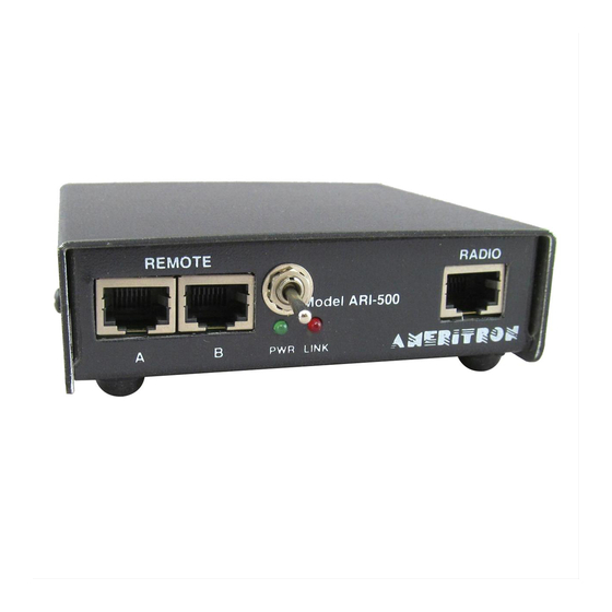
- Page 1 AMERITRON ARI-500 Automatic Band Switch For ALS-500 INSTRUCTION MANUAL PLEASE READ THIS MANUAL BEFORE OPERATING THIS EQUIPMENT ! 116 Willow Road Starkville, MS 39759 USA 662-323-8211 Version 1A Printed in U.S.A.
-
Page 2: Table Of Contents
Specifications......................2 Installation ......................2 Operating ALS-500RC with the ARI-500 ............3 Interfacing ARI-500 to Radio for keying and Band Data …......... 4 Interfacing to Icom Radios ................... 5 Interfacing to Yaesu Radios ................. 6 Interfacing to Kenwood Radios ................7 Operation ...................... -
Page 3: Introduction
2. Ensure the Amplifier switch is off and the frequency select switch is in the Remote position. 3. Plug one of the patch cords into AMP A of the ARI-500. Route the other end to the ALS-500M and connect to Remote A. -
Page 4: Interfacing Ari-500 To Radio For Keying And Band Data
ARI-500 Automatic Band Switch for ALS-500 Instruction Manual Skip this section and go to interfacing ARI-500 to radio for keying and band data, if the ALS-500RC will not be used. The optional ALS-500RC remote head can be used with the ARI-500. The ALS-500RC will display the current, power on, TX and O/L of the amplifier. -
Page 5: Interfacing To Icom Radios
The ARI-500 is designed to operate with only ONE radio. Interfacing to Icom Radios In order to retrieve band data from Icom radios, the ARI-500 must be connected to the band data voltage output. This can be found on the ACC... - Page 6 (goes to ground when the radio is transmitting), power with voltage when on, and ground. The diagram below shows the connections required between an Icom radio and the ARI-500. Connection to an ICOM IC-7000 requires an ICOM approved modification. Follow the instructions included with your IC-7000(page 140) to make the modification.
-
Page 7: Interfacing To Yaesu Radios
CAT port with the Linear port. The radio must be configured so that the port is in Linear mode or the band data information will not be sent to the ARI-500. Check your radio’s manual to determine proper configuration of the Linear port. -
Page 8: Interfacing To Kenwood Radios
Kenwood radio with a DB-9 Com port to the ARI-500. Note that pin 7 and 8 (RTS, CTS) on the Kenwood port are connected together. This ensures that the Kenwood will send the status information to the ARI-500. -
Page 9: Operation
Pin 2 Operation The ARI-500 has an Auto Reset for the amplifier’s load fault (O/L). When the amplifier goes into load fault mode, the ARI-500 will wait 5 seconds and then switch the amplifier’s Power off and back to on for operation. The ARI-500 will reset the amplifier overload up to 3 times in a 5-minute period. -
Page 10: Technical Assistance
Anytime the status of the radio changes, there is a one second delay before the new information is sent over the serial line to the ARI-500. This causes the switch to appear to respond slowly to the band changes. This is a result of the delay from the Kenwood radio, NOT the ARI-500. -
Page 11: Schematic
ARI-500 Automatic Band Switch for ALS-500 Instruction Manual Schematic... - Page 12 ARI-500 Automatic Band Switch for ALS-500 Instruction Manual...
- Page 13 ARI-500 Automatic Band Switch for ALS-500 Instruction Manual...
- Page 14 The serial communications settings are 9600 bps and the linear amplifier relay must be turned on and must be setup on the radio for the ARI-500 to function properly. The serial communications setting is Menu 56 and needs to be set to 9600.
- Page 15 Customers using this manual should report errors omissions, recommendations for improvements, or other comments to Ameritron 116 Willow Road, Starkville, MS 39759. Phone: (662) 323-8211; FAX: (662) 323- 6551. Business hours: M-F 8-4:30 CST.
-
Page 16: Warranty
IMITED ARRANTY Ameritron warrants to the original purchaser that this product shall be free from defects in material or workmanship for one year from the date of original purchase. During the warranty period, Ameritron (or an authorized Ameritron service facility) will provide free of charge both parts and labor necessary to correct defects in material or workmanship.
Need help?
Do you have a question about the ARI-500 and is the answer not in the manual?
Questions and answers