Table of Contents

Related Manuals for AMERITRON RCS-12


Summary of Contents for AMERITRON RCS-12
- Page 1 AMERITRON RCS-12 AUTOMATIC ANTENNA SWITCH INSTRUCTION MANUAL PLEASE READ THIS MANUAL BEFORE OPERATING THIS EQUIPMENT ! 116 Willow Road Starkville, MS 39759 USA 662-323-8211 Version 3B COPYRIGHT C 2005 AMERITRON Printed in U.S.A.
-
Page 2: Table Of Contents
Hot Switch Protection ......................2 Front Panel............................3 Rear Panel ............................3 Installation Powering the RCS-12 ........................4 Connection to Tower Mounted Relay Box ..................4 Using the RCS-10 Relay Box ..................... 4 Using Other Relay Boxes ....................4 Using Direct or Regulated Relay Voltage ................5 Radio Interfacing .......................... -
Page 3: Introduction
Versatile: The RCS-12 will work with the 5 and 8 position tower-mounted relay boxes from Ameritron. However, the RCS-12 will work with any relays using up to 30VDC. Output formats can be 1 of 8, 3 line BCD, or 4 line BCD. -
Page 4: Overview
The RCS-12 will operate with simple push-button operation in Manual mode. In Automatic mode, the RCS-12 reads Band Output Data from the appropriate jack on the back of your transceiver(s). The RCS- 12 is designed to work with most Icom, Yaesu, and Kenwood transceivers. There are separate inputs for each of these input types. -
Page 5: Front Panel
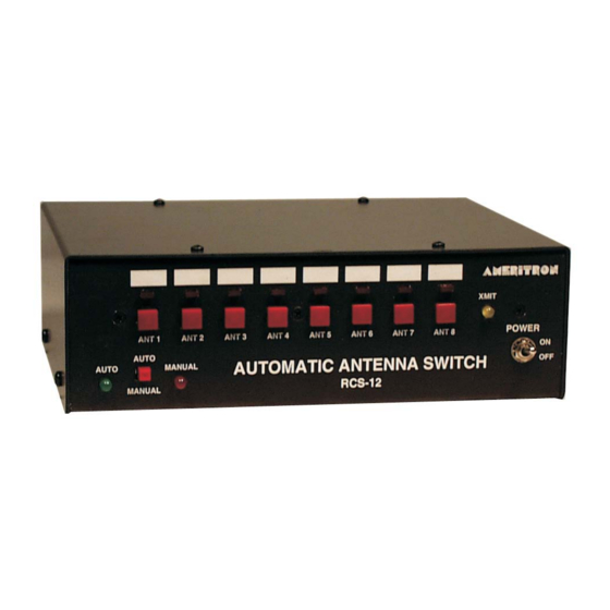
Ameritron RCS-12 Instruction Manual Automatic Antenna Switch RCS-12 Front Panel XMIT ANT 1 ANT 2 ANT 3 ANT 4 ANT 5 ANT 6 ANT 7 POWER AUTO AUTO MANUAL AUTOMATIC ANTENNA SWITCH RCS-12 MANUAL Front Panel Description 1. Power Switch: Unit Power Switch. -
Page 6: Installation
RCS-12. This cable should be fitted with an 8-pin DIN plug on the RCS-12 side and end-stripped on the relay box end so that it may be attached to the terminal strip on the RCS-10 (see the diagrams below and the RCS-10 manual). -
Page 7: Using Direct Or Regulated Relay Voltage
The RCS-12 provides two types of voltages for controlling the relays: Direct or Regulated. The default setting is Direct and uses the power supplied to the RCS-12 to drive the switching relays. The Regulated setting drives the relays using a 12V regulated supply. Selecting the correct modes is accomplished setting JMP 4 located towards the front of the RCS-12. -
Page 8: Radio Interfacing
Ameritron RCS-12 Instruction Manual Automatic Antenna Switch Band Data Voltage Amp Key/HSEND Ground ACC Socket (Rear View) RCS-12 Radio Input (Rear View) Icom Interface to RCS-12 Connection RCS-12 Radio Input Icom ACC Socket Band Data Voltage Pin 5 Pin 5... -
Page 9: Yaesu
The diagram below shows how to connect a Kenwood radio with a DB-9 Com port to the RCS-12. Note that pin 7 and 8 (RTS, CTS) on the Kenwood port are connected together. This ensures that the Kenwood will send the status information to the RCS-12. -
Page 10: Auxiliary Input
Ameritron RCS-12 Instruction Manual Automatic Antenna Switch Auxiliary Input The Auxiliary Input Port allows remote control of the antenna buttons on the antenna switch. The port is a female DB-9 connection with the pin-out shown below. Applying a ground to any of the Aux pins will select the appropriate antenna. -
Page 11: Radio Key In
*Ground is on the shell of the DB-9 plug Radio Key In The Radio Key In jack, when pulled to ground, will prevent the RCS-12 from switching antennas. The Radio Key In jack is +5V open collector and will deliver 1mA when pulled to ground. This jack should be connected to the transceiver’s relay control line that goes to ground on transmit. -
Page 12: Operation
Do not attempt to use this function unless the Amplifier Key Line is connected to the Radio Key In on the rear panel of the RCS-12, or else you will invoke severe damage to your station equipment due to “hot switching.” Make sure the TRANSMIT LED on the front panel of the RCS-12 is always illuminated when transmitting. -
Page 13: Setting Relay Switching Delay
Setting Relay Switching Delay With the power switch off, hold the ANT 1 button while switching the RCS-12 power on. This allows the setting of the relay switching delay. The delay is selected by pressing one of the eight antenna selection buttons. -
Page 14: Technical Assistance
Ameritron at 662-323-8211. You will be best helped if you have your unit, manual and all information on your station handy so you can answer any questions the technicians may ask. - Page 16 IMITED ARRANTY Ameritron warrants to the original purchaser that this product shall be free from defects in material or workmanship for one year from the date of original purchase. During the warranty period, Ameritron (or an authorized Ameritron service facility) will provide free of charge both parts and labor necessary to correct defects in material or workmanship.
Need help?
Do you have a question about the RCS-12 and is the answer not in the manual?
Questions and answers