AMX NXC-IRS4 Installation Manual
4-port ir/s card, 4 ir/s and 4 inputs
Hide thumbs
Also See for NXC-IRS4:
- Operation/reference manual (54 pages) ,
- Specifications (2 pages) ,
- Engineering drawing (1 page)
Table of Contents
Advertisement
Quick Links
NetLinx Control Cards and NetModules
NetLinx Control Cards can be installed in either the NXF CardFrame, NI-4000, or
NetModules. This document provides basic specifications and wiring information for
the NetLinx Control cards. For detailed information on the cards, refer to the NetLinx
CardFrame, Control Cards, and NetModules Instruction Manual.
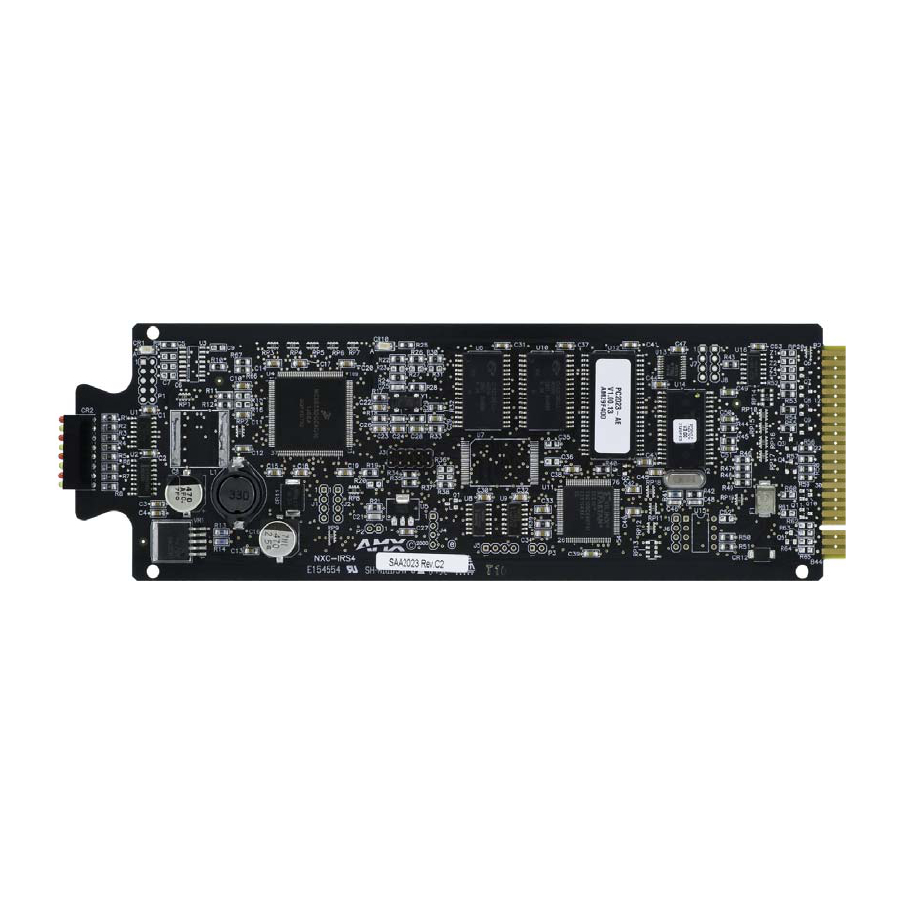
NXC-IRS4 4-Port IR/S Control Card
The NXC-IRS4 4-Port IR/S Control Card provides four IR/Serial output control ports
with LED status feedback. Each port in the NXC-IRS4 stores programmed commands
for IR- or serial-controlled devices.
Specifications
NXC-IRS4 (FG2023) Specifications
Power
110 mA @ +12 VDC power for sensors
Operation:
• IR 1-4: 4 IR/Serial control ports
• Input 1-4: 4 input ports for closure or 0-5 VDC sensing, 200 mA
Memory
32K of IR memory shared between four ports.
IR Frequency range Support of high-frequency carriers up to 1.14 MHz.
Status LEDs:
Red LED shows IR transmission activity / yellow LED shows input
status activity (2 LEDs per channel). LEDs light to indicate ON
status:
• LED 1: Channel 1 Input (yellow)
• LED 2: Channel 1 IR Out (red)
• LED 3: Channel 2 Input (yellow)
• LED 4: Channel 2 IR Out (red)
• LED 5: Channel 3 Input (yellow)
• LED 6: Channel 3 IR Out (red)
• LED 7: Channel 4 Input (yellow)
• LED 8: Channel 4 IR Out (red)
Connections/wiring:
• Two 2-pin 3.5 mm captive-screw terminals
• Two CC-NIRC IR Emitters
Models:
• NXC-IRS4 4-Port IR/S Card
• NXM-IRS4 4-Port IR/S NetModule
DEVICE_ID:
$0108
Pinouts, Signals, and Functions
NXC-IRS4 Pinouts, Signals, and Functions
Pin
Signal
Function
1
GND
Signal ground
2
Output #1
IR data
3
GND
Signal ground
4
Output #2
IR data
5
GND
Signal ground
6
Output #3
IR data
7
GND
Signal ground
8
Output #4
IR data
9
GND
Signal ground
NXC-IRS4 Channel Assignments
The IRS4 channel settings listed in the following table set the IR output channels. The
NXC-IRS4 can process up to two IR or serial device channel setting commands
simultaneously. If more than two device commands are sent simultaneously, only the
first two devices receive the commands.
NXC-IRS4 Channel Assignments
Channel Description
1-255
Generates the IR or serial command assigned to that channel.
1-199
Provides intelligent feedback; if a channel with no IR command is turned on,
the card will turn that channel off.
Ports 1-4
Generates PUSH and RELEASE statements corresponding to the state of
inputs 1 - 4. A contact closure to GND is reported as a PUSH.
• The PUSH and RELEASE channel is 255.
• Channel reporting status is 255.
• Channel 255 changes are disabled after receipt of the 'PON' command.
NXC-IRS4
Pin
Signal
Function
10
Input #1
Logic input
11
Input #2
Logic input
12
Input #3
Logic input
13
Input #4
Logic input
14
Power
+12 VDC
15
---------------
no connection
16
---------------
no connection
17
---------------
no connection
18
---------------
no connection
19
---------------
no connection
20
---------------
no connection
4-Port IR/S Card, 4 IR/S and 4 Inputs
Programming Information
NXC-IRS4 SEND_COMMANDS
CAROFF
Syntax:
Disable the IR carrier
SEND_COMMAND <DEV>,"'CAROFF'"
signal until a 'CARON'
Example:
command is received.
SEND_COMMAND IR_1,"'CAROFF'"
Stops transmitting IR carrier signals to the IR_1 port.
CARON
Syntax:
Enable the IR carrier
SEND_COMMAND <DEV>,"'CARON'"
signals (default).
Example:
SEND_COMMAND IR_1,"'CARON'"
Starts transmitting IR carrier signals to the IR_1 port.
CH
All channels below 100 are transmitted as two digits. If the IR
code for ENTER (function #21) is loaded, an Enter will follow
Send IR pulses for the
the number. If the channel is greater than or equal to (>=) 100,
selected a channel.
then IR function 127 or 20 (whichever exists) is generated for
the one hundred digit. Uses 'CTON' and 'CTOF' times for pulse
times.
Syntax:
SEND_COMMAND <DEV>,"'CH',<Number>"
Channel number = 0 - 199.
Example:
SEND_COMMAND IR_1,"'CH',18"
The NXC-IRS4 performs the following:
• Transmits IR signals for 1 (IR code 11). The transmit time is
set with the CTON command.
• Waits until the time set with the CTOF command elapses.
• Transmits IR signals for 8 (IR code 18).
• Waits for the time set with the CTOF command elapses. If
the IR code for Enter (IR code 21) is programmed, the IRS4
performs the following steps.
• Transmits IR signals for Enter (IR code 21).
• Waits for the time set with the CTOF command elapses.
CP
Syntax:
Halt and Clear all active
SEND_COMMAND <DEV>,"'CP',<code>"
or buffered IR com-
Code = IR port's channel value 0 - 252 (253 - 255 reserved).
mands, and then send a
Example:
single IR pulse. Set the
SEND_COMMAND IR_1,"'CP',2"
Pulse and Wait times
Clears the active/buffered commands and pulses IR_1 port's
with the 'CTON' and
channel 2.
'CTOF' commands.
CTOF
This command sets the delay time between pulses generated
by the 'CH' or 'XCH' send commands in tenths of seconds.
Set the duration of the
Syntax:
Off time (no signal)
between IR pulses for
SEND_COMMAND <DEV>,"'CTOF',<time>"
channel and IR function
Time = 0 - 255. Given in 1/10ths of a second. Default is 5
transmissions.
(0.5 sec).
Off time settings are
Example:
stored in non-volatile
SEND_COMMAND IR_1,"'CTOF',10"
memory.
Sets the Off time between each IR pulse to 1 second.
CTON
This command sets the pulse length for each pulse generated
by the 'CH' or 'XCH' send commands in tenths of seconds.
Set the total time of IR
Syntax:
pulses transmitted and is
stored in non-volatile
SEND_COMMAND <DEV>,"'CTON',<time>"
memory.
Time= 0 - 255. Given in 1/10ths of a second. Default is 5
(0.5 sec).
Example:
SEND_COMMAND IR_1,"'CTON',20"
Sets the IR pulse duration to 2 seconds.
GET MODE
The port responds with: <port #> <mode>,<carrier>,<io link
channel>.
Poll the IR/Serial port's
Syntax:
configuration parame-
ters and report the active
SEND_COMMAND <DEV>,"'GET MODE'"
mode settings to the
Example:
device requesting the
SEND_COMMAND IR_1,"'GET MODE"
information.
The system could respond with:
PORT 4 IR,CARRIER,IO LINK 0
IROFF
Syntax:
Halt and Clear all active
SEND_COMMAND <DEV>,"'IROFF'"
or buffered IR commands
Example:
being output on the
SEND_COMMAND IR_1,"'IROFF"
designated port.
Immediately halts and clears all IR output signals on the IR_1
port.
Installation Guide
Advertisement
Table of Contents

Related Manuals for AMX NXC-IRS4


Summary of Contents for AMX NXC-IRS4
-
Page 1: Programming Information
The IRS4 channel settings listed in the following table set the IR output channels. The NXC-IRS4 can process up to two IR or serial device channel setting commands simultaneously. If more than two device commands are sent simultaneously, only the first two devices receive the commands. - Page 2 ©2007 AMX. All rights reserved. AMX and the AMX logo are registered trademarks of AMX. AMX reserves the right to alter specifications without notice at any time. 3000 RESEARCH DRIVE, RICHARDSON, TX 75082 • 800.222.0193 • fax 469.624.7153 • technical support 800.932.6993 • www.amx.com SET IO LINK...
Need help?
Do you have a question about the NXC-IRS4 and is the answer not in the manual?
Questions and answers