
Related Manuals for Gigabyte GA-8I915P Dual Graphic


Summary of Contents for Gigabyte GA-8I915P Dual Graphic
- Page 1 GA-8I915P Dual Graphic Intel Pentium 4 LGA775 Processor Motherboard ® ® User's Manual Rev. 1002 12ME-8I915PDG-1002...
- Page 3 Gigabyte's prior written permission. Specifications and features are subject to change without prior notice. Product Manual Classification In order to assist in the use of this product, Gigabyte has categorized the user manual in the following: For quick installation, please refer to the "Hardware Installation Guide" included with the product.
-
Page 4: Table Of Contents
Table of Contents GA-8I915P Dual Graphic Motherboard Layout ............. 6 Block Diagram ....................... 7 Chapter 1 Hardware Installation ..................9 Considerations Prior to Installation ..............9 Feature Summary ..................10 Installation of the CPU and Heatsink ............12 1-3-1 Installation of the CPU ..................12 1-3-2 Installation of the Heatsink ................... - Page 5 Chapter 3 Install Drivers .................... 51 Install Chipset Drivers ................... 51 Software Applications ..................52 Driver CD Information ................... 52 Hardware Information ..................53 Contact Us ..................... 53 Chapter 4 Appendix ....................55 Unique Software Utilities ................55 4-1-1 EasyTune 5 Introduction ..................56 4-1-2 Xpress Recovery Introduction ................
-
Page 6: Ga-8I915P Dual Graphic Motherboard Layout
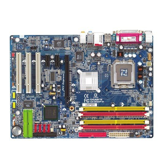
GA-8I915P Dual Graphic Motherboard Layout PWR_FAN KB_MS ATX_12V LGA775 SPDIF_O CPU_FAN SPDIF_I R_USB Intel 915P AUDIO1 AUDIO2 CD_IN NB_FAN AZALIA_FP PCIE_16_1 SYS_FAN Marvell 8001 Main Backup PCIE_1 BIOS BIOS ICH6R PCIE_16_2 F_USB2 CODEC SATA3 F_PANEL PCI1 VT6410 PCI2 TSB43AB23 PCI3... -
Page 7: Block Diagram
Block Diagram CPUCLK+/-(200/133MHz) LGA775 PCI-ECLK Processor (100MHz) PCI-ECLK Host DDR 400/333MHz DIMM (100MHz) Interface PCI-ECLK Dual Channel Memory (100MHz) Intel DDRII 600 /533/400MHz DIMM (Note) 915P PCIE_16_1 Dual Channel Memory MCHCLK (133/200MHz) 66MHz 33MHz 14.318MHz 48MHz Dual BIOS PCI Express x1 Bus 4 Serial ATA Intel ATA33/66/100... - Page 8 - 8 -...
-
Page 9: Chapter 1 Hardware Installation
2. Damage as a result of violating the conditions recommended in the user manual. 3. Damage due to improper installation. 4. Damage due to use of uncertified components. 5. Damage due to use exceeding the permitted parameters. 6. Product determined to be an unofficial Gigabyte product. - 9 - Hardware Installation... -
Page 10: Feature Summary
For example, 4 GB of memory size will instead be shown as 3.xxGB memory during system startup. (Note 2) To use a DDRII 600 memory module on the motherboard, you must install an 800MHz FSB processor and overclock in BIOS. (Note 3) Only support ATAPI mode for HDD. GA-8I915P Dual Graphic Motherboard - 10 -... - Page 11 Onboard Audio C-Media 9880 CODEC Supports Jack Sensing function Supports 2 / 4 / 5.1 / 7.1 channel audio Supports Line In ; Line Out ; MIC ; Back Surround Speaker Out ; Center/Subwoofer Speaker Out ; Surround Speaker Out connection Supports SPDIF In/Out connection CD In On-Board SATA RAID...
-
Page 12: Installation Of The Cpu And Heatsink
(Grasping the CPU firmly between your thumb and forefinger, carefully place it into the socket in a straight and downwards motion. Avoid twisting or bending motions that might cause damage to the CPU during installation.) GA-8I915P Dual Graphic Motherboard - 12 -... -
Page 13: Installation Of The Heatsink
1-3-2 Installation of the Heatsink Male Push Pin The top of Female Push Pin Female Push Pin Fig.1 Fig. 2 Please apply an even layer of heatsink paste on (Turning the push pin along the direction of arrow is the surface of the installed CPU. to remove the heatsink, on the contrary, is to install.) Please note the direction of arrow sign on the male push pin doesn't face inwards before installation. -
Page 14: Installation Of Memory
DIMM socket. Then push it down. Fig.2 Close the plastic clip at both edges of the DIMM sockets to lock the DIMM module. Reverse the installation steps when you wish to remove the DIMM module. GA-8I915P Dual Graphic Motherboard - 14 -... - Page 15 Dual Channel DDR/DDR II The GA-8I915P Dual Graphic supports the Dual Channel Technology. When the Dual Channel Technology is activated, the bandwidth of memory bus will be double the original one. Due to chipset limitation, if you want to operate the Dual Channel Technology, please follow the guidelines below for Dual Channel memory configuration.
-
Page 16: Installation Of Expansion Cards
.Make sure your VGA card is locked by the small white-drawable bar. The GA-8I915P Dual Graphic will allow a four-monitor configuration(Quad View) when used in conjunction with two PCI Express graphics cards that are based on identical chips and support dual view. -
Page 17: Configuring A Quad View System
This function is supported only on Windows XP operating system. With Quad View technology from GIGABYTE, Dual Graphic enabled motherboards offer multiple display support on up to four separate monitors. This improves the capabilities and productivity of the user by allowing them to spread multiple windows over four monitors and view them simultaneously. - Page 18 PEG2 if the card is installed in the PCIE_16_2 slot. Step 3: Graphics Cards Driver Setting For detailed information about how to install the graphics card driver, please refer to the user’s manual for your graphics card. GA-8I915P Dual Graphic Motherboard - 18 -...
-
Page 19: I/O Back Panel Introduction
I/O Back Panel Introduction PS/2 Keyboard and PS/2 Mouse Connector To install a PS/2 port keyboard and mouse, plug the mouse to the upper port (green) and the keyboard to the lower port (purple). Parallel Port The parallel port allows connection of a printer, scanner and other peripheral devices. SPDIF_O (SPDIF Out) The SPDIF output is capable of providing digital audio to external speakers or compressed AC3 data to an external Dolby Digital Decoder. -
Page 20: Connectors Introduction
You can use audio software to configure 2-/4-/5.1-/7.1-channel audio functioning. Connectors Introduction ATX_12V PWR_LED ATX (Power Connector) F_PANEL CPU_FAN AZALIA_FP SYS_FAN CD_IN PWR_FAN F_USB1 / F_USB2 NB_FAN F1_1394 / F2_1394 IDE1 CLR_CMOS IDE2/IDE3 SATA0 / SATA1 / SATA2 / SATA3 GA-8I915P Dual Graphic Motherboard - 20 -... - Page 21 1/2) ATX_12V/ATX (Power Connector) With the use of the power connector, the power supply can supply enough stable power to all the components on the motherboard. Before connecting the power connector, please make sure that all components and devices are properly installed. Align the power connector with its proper location on the motherboard and connect tightly.
- Page 22 (Only for CPU_FAN) SYS_FAN 6) NB_FAN (Chip Fan Connector) If you installed wrong direction, the chip fan will not work. Sometimes will damage the chip fan. (Usually black cable is GND) Pin No. Definition +12V GA-8I915P Dual Graphic Motherboard - 22 -...
- Page 23 7) FDD (Floppy Connector) The FDD connector is used to connect the FDD cable while the other end of the cable connects to the FDD drive. The types of FDD drives supported are: 360KB, 720KB, 1.2MB, 1.44MB and 2.88MB. Please connect the red power connector wire to the pin1 position. 8/9) IDE1/IDE2/IDE3 (IDE Connector) An IDE device connects to the computer via an IDE connector.
- Page 24 Definition 11) PWR_LED PWR_LED is connect with the system power indicator to indicate whether the system is on/off. It will blink when the system enters suspend mode. Pin No. Definition MPD+ MPD- MPD- GA-8I915P Dual Graphic Motherboard - 24 -...
- Page 25 12) F_PANEL (Front Panel Jumper) Please connect the power LED, PC speaker, reset switch and power switch etc of your chassis front panel to the F_PANEL connector according to the pin assignment below. Speaker Connector SPEAK- Reset Switch SPEAK+ RES+ Power Switch RES- MSG-...
- Page 26 HD Audio is the default setting for this connector. To enable AC'97 Audio, from BIOS settings, set Front Panel Type under Integrated Peripherals to AC97. 14) CD_IN (CD IN) Connect CD-ROM or DVD-ROM audio out to the connector. Pin No. Definition CD-L CD-R GA-8I915P Dual Graphic Motherboard - 26 -...
- Page 27 15) F_ USB1 / F_USB2 (Front USB Connector) Be careful with the polarity of the front USB connector. Check the pin assignment carefully while you connect the front USB cable, incorrect connection between the cable and connector will make the device unable to work or even damage it. For optional front USB cable, please contact your local dealer.
- Page 28 You may clear the CMOS data to its default values by this jumper. To clear CMOS, temporarily short 1-2 pin. Default doesn't include the "Shunter" to prevent from improper use this jumper. Open: Normal Short: Clear CMOS GA-8I915P Dual Graphic Motherboard - 28 -...
- Page 29 19) BAT(Battery) Danger of explosion if battery is incorrectly replaced. Replace only with the same or equivalent type recommended by the manufacturer. Dispose of used batteries according to the manufacturer's instructions. If you want to erase CMOS... 1.Turn OFF the computer and unplug the power cord. 2.Remove the battery, wait for 30 second.
- Page 30 GA-8I915P Dual Graphic Motherboard - 30 -...
-
Page 31: Chapter 2 Bios Setup
BIOS needs to be reset to its original settings. If you wish to upgrade to a new BIOS, either Gigabyte's Q-Flash or @BIOS utility can be used. Q-Flash allows the user to quickly and easily update or backup BIOS without entering the operating system. -
Page 32: The Main Menu (For Example: Bios Ver. : F1)
MB Intelligent Tweaker(M.I.T.) This setup page is control CPU clock and frequency ratio. Load Fail-Safe Defaults Fail-Safe Defaults indicates the value of the system parameters which the system would be in safe configuration. GA-8I915P Dual Graphic Motherboard - 32 -... - Page 33 Load Optimized Defaults Optimized Defaults indicates the value of the system parameters which the system would be in best performance configuration. Set Supervisor Password Change, set, or disable password. It allows you to limit access to the system and Setup, or just to Setup. Set User Password Change, set, or disable password.
-
Page 34: Standard Cmos Features
Cylinder Number of cylinders Head Number of heads Precomp Write precomp Landing Zone Landing zone Sector Number of sectors If a hard disk has not been installed, select NONE and press <Enter>. GA-8I915P Dual Graphic Motherboard - 34 -... - Page 35 Drive A / Drive B The category identifies the types of floppy disk drive A or drive B that has been installed in the computer. None No floppy drive installed 360K, 5.25" 5.25 inch PC-type standard drive; 360K byte capacity. 1.2M, 5.25"...
-
Page 36: Advanced Bios Features
Select your boot device priority by USB-HDD. Select your boot device priority by LAN. Disabled Select your boot device priority by Disabled. (Note) This item will show up when you install a processor which supports this function. GA-8I915P Dual Graphic Motherboard - 36 -... - Page 37 Password Check Setup The system will boot but will not access to Setup page if the correct password is not entered at the prompt. (Default value) System The system will not boot and will not access to Setup page if the correct password is not entered at the prompt.
-
Page 38: Integrated Peripherals
Disable onboard 1st channel IDE port. SATA RAID / AHCI Mode RAID Select onboard Seria ATA function as RAID. (Default value) AHCI Support hotplug function under OS. WinXP,2000 only. Disabled Select onboard Seria ATA function as ATA. GA-8I915P Dual Graphic Motherboard - 38 -... - Page 39 On-Chip SATA Mode Disabled Disable this function. Auto BIOS will auto detect. (Default value) Combined Set On-Chip SATA mode to Combined, you can use up to 4 HDDs on the motherboard; 2 for SATA and the other for PATA IDE. Enhanced Set On-Chip SATA mode to Enhanced, the motherboard allows up to 6 HDDs to use.
- Page 40 UR2 Duplex Mode This feature allows you to seclect IR mode. This function will available when "UART Mode Select" doesn't set at Normal. Half IR Function Duplex Half. (Default value) Full IR Function Duplex Full. GA-8I915P Dual Graphic Motherboard - 40 -...
- Page 41 Onboard Parallel port Disabled Disable onboard LPT port. 378/IRQ7 Enable onboard LPT port and address is 378/IRQ7. (Default value) 278/IRQ5 Enable onboard LPT port and address is 278/IRQ5. 3BC/IRQ7 Enable onboard LPT port and address is 3BC/IRQ7. Parallel Port Mode Using Parallel port as Standard Parallel Port.
-
Page 42: Power Management Setup
Time (hh: mm: ss) Alarm : (0~23) : (0~59) : (0~59) Power On By Mouse Disabled Disable this function. (Default value) Double Click Double click on PS/2 mouse left button to power on the system. GA-8I915P Dual Graphic Motherboard - 42 -... - Page 43 Power On By Keyboard Password Enter from 1 to 5 characters to set the Keyboard Power On Password. Disabled Disabled this function. (Default value) Keyboard 98 If your keyboard have "POWER Key" button, you can press the key to power on the system. KB Power ON Password When "Power On by Keyboard"...
-
Page 44: Pnp/Pci Configurations
Auto assign IRQ to PCI 2. (Default value) 3,4,5,7,9,10,11,12,14,15 Set IRQ 3,4,5,7,9,10,11,12,14,15 to PCI 2. PCI 3 IRQ Assignment Auto Auto assign IRQ to PCI 3. (Default value) 3,4,5,7,9,10,11,12,14,15 Set IRQ 3,4,5,7,9,10,11,12,14,15 to PCI 3. GA-8I915P Dual Graphic Motherboard - 44 -... -
Page 45: Pc Health Status
PC Health Status CMOS Setup Utility-Copyright (C) 1984-2004 Award Software PC Health Status Vcore Item Help DDRV Menu Level +3.3V +12V Current CPU Temperature Current CPU FAN Speed 4687 RPM Current POWER FAN Speed Current SYSTEM FAN Speed CPU Warning Temperature [Disabled] CPU FAN Fail Warning [Disabled]... -
Page 46: Mb Intelligent Tweaker(M.i.t.)
C.I.A.2 (CPU Intelligent Acelerator 2) is designed to detect CPU loading during software program executing, and automatically adjust CPU computing power to maximize system performance. Disabled Disable this function. (Default value) Cruise Set C.I.A.2 to Cruise. (Automatically increase CPU frequency(5%,7%) by CPU loading. GA-8I915P Dual Graphic Motherboard - 46 -... - Page 47 Sports Set C.I.A.2 to Sports. (Automatically increase CPU frequency(7%,9%) by CPU loading. Racing Set C.I.A.2 to Racing. (Automatically increase CPU frequency(9%,11%) by CPU loading. Turbo Set C.I.A.2 to Turbo. (Automatically increase CPU frequency(15%,17%) by CPU loading. Full Thrust Set C.I.A.2 to Full Thrust. (Automatically increase CPU frequency(17%,19%) by CPU loading.
-
Page 48: Load Fail-Safe Defaults
MB Intelligent Tweaker(M.I.T.) ESC: Quit : Select Item F8: Dual BIOS/Q-Flash F10: Save & Exit Setup Load Fail-Safe Defaults Fail-Safe defaults contain the most appropriate values of the system parameters that allow minimum system performance. GA-8I915P Dual Graphic Motherboard - 48 -... -
Page 49: Load Optimized Defaults
Load Optimized Defaults CMOS Setup Utility-Copyright (C) 1984-2004 Award Software Standard CMOS Features Load Fail-Safe Defaults Advanced BIOS Features Load Optimized Defaults Integrated Peripherals Set Supervisor Password Power Management Setup Set User Password Load Optimized Defaults (Y/N)? N PnP/PCI Configurations Save &... -
Page 50: Save & Exit Setup
: Select Item F8: Dual BIOS/Q-Flash F10: Save & Exit Setup Abandon all Data Type "Y" will quit the Setup Utility without saving to RTC CMOS. Type "N" will return to Setup Utility. GA-8I915P Dual Graphic Motherboard - 50 -... -
Page 51: Chapter 3 Install Drivers
Chapter 3 Install Drivers Pictures below are shown in Windows XP. Insert the driver CD-title that came with your motherboard into your CD-ROM drive, the driver CD-title will auto start and show the installation guide. If not, please double click the CD-ROM device icon in "My computer", and execute the Run.exe. -
Page 52: Software Applications
Software Applications This page displays all the tools that Gigabyte developed and some free software, you can choose anyone you want and press "install" to install them. Driver CD Information This page lists the contents of software and drivers in this CD-title. -
Page 53: Hardware Information
Hardware Information This page lists all device you have for this motherboard. Contact Us Please see the last page for details. - 53 - Install Drivers... - Page 54 GA-8I915P Dual Graphic Motherboard - 54 -...
-
Page 55: Chapter 4 Appendix
Motherboard Intelligent Tweaker (M.I.T.) allows user to access and change BIOS feature settings with relative speed and ease. Through GIGABYTE M.I.T. feature the user is no longer required to switch into different modes within BIOS setup in order to change system settings such as the CPU system bus, memory timings or to enabled Gigabyte's unique C.I.A. -
Page 56: Easytune 5 Introduction
Toggles between Easy and Advance Mode Display screen Display panel of CPU frequency Function display LEDs Shows the current functions status GIGABYTE Logo Log on to GIGABYTE website Help button Display EasyTune 5 Help file Exit or Minimize button Quit or Minimize EasyTune... -
Page 57: Xpress Recovery Introduction
F9 key during computer power on. Verifying DMI Pool Data Boot from CD: Boot from CD: Xpress Recovery V1.0 (C) Copy Right 2003. GIGABYTE Technology CO. , Ltd. 1. Execute Backup Utility 2. Execute Restore Utility 3. Remove Backup Image 4. - Page 58 F9 For Xpress Recovery Press DEL to enter SETUP / Q-Flash, F9 For Xpress Recovery 08/16/2002-I845GE-6A69YG01C-00 Xpress Recovery V1.0 (C) Copy Right 2003. GIGABYTE Technology CO. , Ltd. 1. Execute Backup Utility 2. Execute Restore Utility 3. Remove Backup Image 4.
- Page 59 1. Execute Backup Utility: Press B to Backup your System or Esc to Exit The backup utility will automatically scan your system and back up data as a backup image in your hard drive. Not all systems support access to Xpress Recovery by pressing the F9 key during computer power on.
-
Page 60: Flash Bios Method Introduction
Save Settings to CMOS Q-Flash Utility Update Main BIOS from Floppy Update Backup BIOS from Floppy Save Main BIOS to Floppy Save Backup BIOS to Floppy PgDn/PgUp: Modify : Move ESC: Reset F10: Power Off GA-8I915P Dual Graphic Motherboard - 60 -... - Page 61 Dual BIOS Item explanation: Wide Range Protection: Disable(Default), Enable Status 1: If any failure (ex. Update ESCD failure, checksum error or reset? occurs in the Main BIOS, just before the Operating System is loaded and after the power is on, and that the Wide Range Protection is set to "Enable", the PC will boot from Backup BIOS automatically.
- Page 62 Updating BIOS with Q-Flash Utility on Dual BIOS Motherboards. Some of Gigabyte motherboards are equipped with dual BIOS. In the BIOS menu of the motherboards supporting Q-Flash and Dual BIOS, the Q-Flash utility and Dual BIOS utility are combined in the same screen.
- Page 63 Entering the Q-Flash utility: Step1: To use Q-Flash utility, you must press Del in the boot screen to enter BIOS menu. CMOS Setup Utility-Copyright (C) 1984-2004 Award Software Standard CMOS Features Select Language Advanced BIOS Features Load Fail-Safe Defaults Integrated Peripherals Load Optimized Defaults Power Management Setup Set Supervisor Password...
- Page 64 Save Main BIOS to Floppy Save Backup BIOS to Floppy Enter : Run :Move ESC:Reset F10:Power Off After BIOS file is read, you'll see a confirmation dialog box asking you "Are you sure to update BIOS?" GA-8I915P Dual Graphic Motherboard - 64 -...
- Page 65 3. Press Y button on your keyboard after you are sure to update BIOS. Then it will begin to update BIOS. The progress of updating BIOS will be displayed. Please do not take out the floppy disk when it begins flashing BIOS. 4.
- Page 66 Set User Password PC Health Status Save & Exit Setup MB Intelligent Tweaker(M.I.T.) Exit Without Saving ESC: Quit F3: Change Language F8: Q-Flash F10: Save & Exit Setup Time, Date, Hard Disk Type... GA-8I915P Dual Graphic Motherboard - 66 -...
- Page 67 Exploring the Q-Flash utility screen The Q-FlashBIOS utility screen consists of the following key components. Q-Flash utility bar Q-Flash Utility V1.30 Flash Type/Size.........SST 49LF003A 256K Keep DMI Data Enable Task menu for Update BIOS from Floppy Q-Flash utility Save BIOS to Floppy Action bar Enter : Run :Move...
- Page 68 Press Del to enter BIOS menu after system reboots and "Load BIOS Fail-Safe Defaults". See how to Load BIOS Fail-Safe Defaults, please kindly refer to Step 6 to 7 in Part One. Congratulation!! You have updated BIOS successfully!! GA-8I915P Dual Graphic Motherboard - 68 -...
- Page 69 Windows. Just select the desired @BIOS server to download the latest version of BIOS. Fig 1. Installing the @BIOS utility Fig 2. Installation Complete and Run @BIOS Click Sart/ Programs/ GIGABYTE/@BIOS Select @BIOS item than click Install Fig 3. The @BIOS Utility Fig 4. Select the desired @BIOS server Click "...
- Page 70 III. In method I, if the BIOS file you need cannot be found in @BIOSTM server, please go onto Gigabyte's web site for downloading and updating it according to method II. IV. Please note that any interruption during updating will cause system unbooted...
-
Page 71: Serial Ata Bios Setting Utility Introduction
4-1-4 Serial ATA BIOS Setting Utility Introduction RAID Levels RAID (Redundant Array of Independent Disks) is a method of combining two hard disk drives into one logical unit. The advantage of an Array is to provide better performance or data fault tolerance. Fault tolerance is achieved through data redundant operation, where if one drives fails, a mirrored copy of the data can be found on another drive. - Page 72 [ DISK/VOLUME INFORMATION ] RAID Volumes : None Defined. Physical Disks : Port Driver Model Serial # Size Type/Status(Vol ID) ST3120026AS 3JT354CP 111.7GB Non-RAID Disk ST3120026AS 3JT329JX 111.7GB Non-RAID Disk ]-Select [ESC]-Exit [ENTER]-Select Menu GA-8I915P Dual Graphic Motherboard - 72 -...
- Page 73 Create RAID Volume Press Enter under Create RAID Volume to set up RAID. Intel(R) Application Accelerator RAID Option ROM v4.0.6180 Copyright(C) 2003-04 Intel Corporation. All Rights Reversed. [ CREATE VOLUME MENU ] Name : RAID_Volume0 RAID Level : RAID0(Stripe) Disks : Select Disks Strip Size : 128KB...
- Page 74 ]-Change [TAB]-Next [ESC]-Previous Menu [ENTER]-Select Press Enter to enter Create Volume after setting disk capacity. GA-8I915P Dual Graphic Motherboard - 74 -...
- Page 75 Press Enter under the Create Volume item. Intel(R) Application Accelerator RAID Option ROM v4.0.6180 Copyright(C) 2003-04 Intel Corporation. All Rights Reversed. [ CREATE VOLUME MENU ] Name : RAID_Volume0 RAID Level : RAID0(Stripe) Disks : Select Disks Strip Size : 128KB Capacity : 223.5 GB...
- Page 76 Size Status Bootable RAID_Volume0 RAID(Stripe) 128KB 223.5GB Normal Physical Disks : Port Driver Model Serial # Size Type/Status(Vol ID) ST3120026AS 3JT354CP 111.7GB Member Disk(0) ST3120026AS 3JT329JX 111.7GB Member Disk(0) ]-Select [ESC]-Exit [ENTER]-Select Menu GA-8I915P Dual Graphic Motherboard - 76 -...
- Page 77 Installing the RAID drivers To install Windows 2000/XP onto a Serial ATA hard disk sucessfully, you need to install required driver for the SATA controller on your motherboard during OS installation. Without the driver, the hard disk may not be recognized during the Windows setup process.
-
Page 78: / 5.1 / 7.1 Channel Audio Function Introduction
(e.g. if back surround speakers are configured, then the system will be in 7.1 channel output mode no matter what other output devices are configured.) GA-8I915P Dual Graphic Motherboard - 78 -... - Page 79 2 Channel Audio Setup: We recommend that you use speakers with amplifier to acquire the best sound effect if the stereo output is applied. STEP 1: Connect the stereo speakers or earphone to "Line Out". Line Out STEP 2: After installation of the audio driver, you'll find an icon in the system area.
- Page 80 "Audio System Status". "Smart Jack" would auto-detect the speaker type you connect and gives you the functions to manually modify speaker the settings. The function to manually modify speaker setting. The function to adjust speaker volume. GA-8I915P Dual Graphic Motherboard - 80 -...
- Page 81 5.1 Channel Audio Setup STEP 1 : Front Speaker Out Connect the front speaker to "Front Speaker Out", the Center/Subwoofer surround speaker to "Surround speaker out", and the Speaker Out center/subwoofer speaker to "Center/Subwoofer Surround speaker Speaker Out". STEP 2: After installation of the audio driver, you find an icon in the system area.
- Page 82 "Audio System Status". "Smart Jack" would auto-detect the speaker type you connect and gives you the functions to manually modify speaker the settings. The function to manually modify speaker setting. The function to adjust speaker volume. GA-8I915P Dual Graphic Motherboard - 82 -...
- Page 83 Digital I/O Status: Digital Output Status-- (1) For stereo PCM output: sampling rate is shown here. (2) For Dolby Digital Live! output: AC3 is shown here. Digital Input Status-- (1) For stereo PCM input: sampling rate is shown here. Mixer The build-in mixer allows users to control volume and monitor sound recording.
-
Page 84: Troubleshooting
Question 6: How do I disable onboard VGA card in order to add an external VGA card? Answer: Gigabyte motherboards will auto-detect the external VGA card after it is plugged in, so you don't need to change any setting manually to disable the onboard VGA. - Page 85 Question 7: Why cannot I use the IDE 2? Answer: Please refer to the user manual and check whether you have connected any cable that is not provided with the motherboard package to the USB Over Current pin in the Front USB Panel. If the cable is your own cable, please remove it from this pin and do not connect any of your own cables to it.
- Page 86 GA-8I915P Dual Graphic Motherboard - 86 -...
- Page 87 Contact Us Taiwan (Headquarters) Japan GIGA-BYTE TECHNOLOGY CO., LTD. NIPPON GIGA-BYTE CORPORATION Address: No.6, Bau Chiang Road, Hsin-Tien, Taipei Hsien, WEB address : http://www.gigabyte.co.jp Taiwan Singapore TEL: +886 (2) 8912-4888 GIGA-BYTE SINGAPORE PTE. LTD. FAX: +886 (2) 8912-4003 Tech. Support : Tech.
- Page 88 WEB address : http://www.gigabyte.ru Xian Poland TEL: +86-029-85531943 Representative Office Of Giga-Byte Technology Co., Ltd. FAX: +86-029-85539821 POLAND Shenyang Tech. Support : TEL: +86-024-23960918 http://tw.giga-byte.com/TechSupport/ServiceCenter.htm FAX: +86-024-23960918-809 Non-Tech. Support(Sales/Marketing) : http://ggts.gigabyte.com.tw/nontech.asp WEB address : http://www.gigabyte.pl GA-8I915P Dual Graphic Motherboard - 88 -...
Need help?
Do you have a question about the GA-8I915P Dual Graphic and is the answer not in the manual?
Questions and answers