Table of Contents
Advertisement
Quick Links
USER'S MANUAL 990-057
Revision K, May 2004
Use with Firmware Release V1.19 or higher
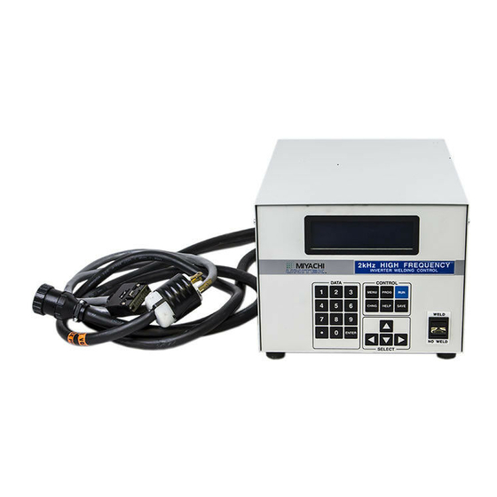
RESISTANCE WELDING POWER SUPPLY
Units with the built-in Weld Sentry Option also require User's Manual No. 990-291
MODEL HF2
2 kHz HIGH FREQUENCY
MODEL NUMBER
HF2/230
HF2/380
HF2/460
HF2/208
HF2S/230
HF2S/380
HF2S/460
HF2S/208
Please be sure to read all personnel and equipment
safety precautions noted in this manual.
STOCK NUMBER
1-264-03
1-264-03-01
1-264-03-02
1-264-03-03
1-265-03
1-265-03-01
1-265-03-02
1-265-03-03
WARNING
Advertisement
Table of Contents

Related Manuals for Unitek HF2/230


Summary of Contents for Unitek HF2/230
- Page 1 USER'S MANUAL 990-057 Revision K, May 2004 Use with Firmware Release V1.19 or higher MODEL HF2 2 kHz HIGH FREQUENCY RESISTANCE WELDING POWER SUPPLY MODEL NUMBER STOCK NUMBER HF2/230 1-264-03 HF2/380 1-264-03-01 HF2/460 1-264-03-02 HF2/208 1-264-03-03 HF2S/230 1-265-03 HF2S/380 1-265-03-01...
- Page 2 1998, 2002 Unitek Miyachi Corporation The engineering designs, drawings and data contained herein are the proprietary work of UNITEK MIYACHI CORPORATION and may not be reproduced, copied, exhibited or otherwise used without the written authorization of UNITEK MIYACHI CORPORATION. Printed in the United States of America.
- Page 3 FOREWORD The purpose of this manual is to supply operating, maintenance and service personnel with the information needed to properly and safely operate, maintain and service the Unitek Peco Model HF2 2 kHz High Frequency Resistance Welding Power Supply. Should questions arise, or if you have suggestions for improving this manual, please contact:...
-
Page 4: Table Of Contents
Weld Head Set-Up..........................3-2 Firing Switch Cable Connection....................... 3-2 Quick Start Programming Guide ..................... 3-2 Unitek Peco Force Fired, Single Air Actuated Weld Head System ............3-4 Weld Head Set-Up..........................3-4 Firing Switch Cable Connection....................... 3-4 Weld Head Valve Driver No. 1 Connection .................... 3-4 Foot Switch Connection ........................ - Page 5 CONTENTS (Continued) Page CHAPTER 3: WELDING SYSTEM SET-UP (Continued) Weld Head Valve Driver Connections ..................3-10 Foot Switch Connection ......................... 3-10 Dual Air Regulator Adjustments ....................3-11 Quick Start Programming Guide ....................3-15 Non-Force Fired, Single Air or Cam Actuated Weld Head System..........3-17 LC To HF2 Control Electrical Connections ..................
- Page 6 CONTENTS (Continued) Page CHAPTER 5: PROGRAMMING MODES..................5-1 Help Screens ............................5-1 Machine States ............................5-1 Weld Graph Run State ..........................5-1 Basic Weld Monitor Run State ........................ 5-2 Alphanumeric Run State .......................... 5-2 No Weld State ............................5-2 Standby State ............................5-2 Alarm State .............................
- Page 7 CONTENTS (Continued) Page CHAPTER 8: WELD MONITORING ....................8-1 Basic Weld Monitor General Description....................8-1 Weld Current and Weld Voltage Measurements ..................8-2 Data Output Capabilities ......................... 8-2 Weld Monitoring Suggestions ......................... 8-2 Basic Weld Monitor Programming......................8-3 Energy Limit Monitor General Description..................... 8-4 Energy Limit Monitor Programming .......................
-
Page 9: Chapter 1: Description
CHAPTER 1 DESCRIPTION The Unitek Peco High Frequency Inverter (HF2) is a 2 KHz, three-phase, state-of-the-art inverter welding control for joining precision small parts at high speed with controllable rise times using 2 KHz output pulses superimposed on pure DC welding energy. High speed (250 micro-second) digital feedback automatically controls weld current, voltage, or power, providing more welding consistency compared to traditional direct energy (AC) or stored energy (CD) technologies. -
Page 11: Chapter 2: General Set-Up
REQUIRED CONNECTIONS Physical Space Requirements Unitek Peco recommends that the HF2 Weld Control and HF2 Weld Transformer be installed in a well ventilated area that is free from excessive dust, acids, corrosive gases, salt and moisture. Allow sufficient clearance around both sides and back of the HF2 Weld Control and HF2 Weld Transformer so that cooling air may flow properly. -
Page 12: Power Line Voltage, Current, And Wire Size Requirements
Use the following table to select the correct power line circuit breaker and wire gauge size. To minimize peak power losses, use single unbroken wire lines. Note: To minimize peak power losses, Unitek Peco recommended wire gauge sizes exceed the USA National Electrical Code recommendations. -
Page 13: Hf2 Weld Transformer Electrical Specifications
CHAPTER 2: GENERAL SETUP HF2 Weld Transformer Electrical Specifications Model Input Volts Input kva Duty Cycle ( %) Peak Open Ckt Peak Output Max Sec (Rms) (Rms) Output Voltage Max. (Amps) Resist. (μΩ) X3/4/380A 4,000 X3/4/460A 4,000 X3/4000A 4,000 X9/6000A 9.3 (32:1 TR) 4,900 X11/4/460A... -
Page 14: Hf2 Welding System Maximum Secondary Loop Resistance
CHAPTER 2: GENERAL SETUP HF2 Welding System Maximum Secondary Loop Resistance To use the HF2 Weld Control and HF2 Weld Transformer system to its maximum capability, the Maximum Secondary Loop Resistance must not exceed the values listed in the preceding table. Exceeding these maximums will produce a "FEEDBACK RANGE EXCEEDED"... -
Page 15: Hf2 Weld Transformer To Weld Head Connections
CHAPTER 2: GENERAL SETUP HF2 Weld Transformer to Weld Head Connections (Figure 2-6) Connect the Upper Weld Cable to the Positive Terminal on the HF2 Weld Transformer. Connect the Lower Weld Cable to the Negative Terminal on the HF2 Weld Transformer. -
Page 17: Chapter 3: Welding System Set-Up
Welding System Set-Up Guide Page Unitek Equipment Force Fired, Foot Actuated Weld Head Unitek Equipment Force Fired, Single Air Actuated Weld Head Unitek Equipment Force Fired, Dual Air Actuated Weld Head Non-Force Fired, Single Air or Cam Actuated Weld Head... -
Page 18: Weld Head Set-Up
CHAPTER 3: WELDING SYSTEM SET-UP UNITEK EQUIPMENT FORCE FIRED, FOOT ACTUATED WELD HEAD SYSTEM Weld Head Set-up Adjust the Weld Head Force Adjust Knob to produce 5 units of force as displayed on the Force Indicator. For a complete description of force control and its effect on the welding process, please refer to your Weld Head manual. - Page 19 CHAPTER 3: WELDING SYSTEM SET-UP Select TRANSFORMER MODEL. The TRANSFORMER MODEL screen appears. Select MULTIPLE HEADS: OFF. If the display reads ON, then press [CHNG] until OFF is displayed. Select HEAD 1 : X3/4000-230. X3/4000-230 is the default Transformer Model number. Press [CHNG] until the correct Transformer Model that you have purchased appears.
-
Page 20: Weld Head Set-Up
Connect a Model FS1L, 1-Level, or a Model FS2L, 2-Level Foot Switch to the FOOT SWITCH connector located on the HF2 rear panel. The HF2 will automatically recognize which model of Unitek Equipment Foot Switch has been connected. 1-Level Foot Switch - The l-Level Foot Switch must be fully depressed by the operator. When the Foot Switch closes, the HF2 energizes the Air Actuated Weld Head, causing the Upper Electrode to descend and apply force to the parts. -
Page 21: Single Air Regulator Adjustment (Model 80 Series)
CHAPTER 3: WELDING SYSTEM SET-UP 3 2-Level Foot Switch - When a 2-Level Foot Switch is pressed to the first level, the HF2 energizes the Air Actuated Weld Head, causing the Upper Electrode to descend and apply force to the parts. If the Foot Switch is released before the operator presses the Foot Switch to the second level, the HF2 will automatically return the Upper Electrode to its up position so that the parts can be repositioned. -
Page 22: Dual Air Regulator Adjustments (Model 180 And Model 90 Series)
CHAPTER 3: WELDING SYSTEM SET-UP Adjust the Down Speed Control Knob so the Upper Electrode descends smoothly onto the parts. Adjust the Up Speed Control Knob so that the Upper Electrode Holder does not impact upon returning to in "up position". Dual Air Regulator Adjustments (Model 180 Series and Model 90 Series Weld Heads - Figure 3-2) Turn the Air Regulator located on the right-hand side of the Weld Head Clockwise (CW) to... - Page 23 CHAPTER 3: WELDING SYSTEM SET-UP Press [SAVE] to save your program. You are now back in the Weld Graph RUN State. 10 Make additional test welds and then re-program WELD time and weld CURRENT as necessary to make a good weld. Strive to use minimum time and current necessary to make a good weld so that the weld joint heat affected zone will be minimized.
-
Page 24: General Information
CHAPTER 3: WELDING SYSTEM SET-UP UNITEK EQUIPMENT FORCE FIRED, DUAL AIR ACTUATED WELD HEAD SYSTEM General Information Dual Air Actuated Weld Head System operation uses sequential action to activate one Weld Head and then a second weld head using a single HF2 Weld Control and HF2 Weld Transformer. The operator must close and release the Foot Switch to initiate each sequential weld. -
Page 25: Firing Switch Cable Connection
CHAPTER 3: WELDING SYSTEM SET-UP Figure 3-4. Weld Cable and Air Line Connections for Dual Air Actuated Weld Heads Connect a properly filtered air line to the Inlet Air Line on the Weld Head Air Valve Driver Solenoid assembly which is located on the back of the Weld Head. Use 0.25 inch O.D. by 0.17 inch I.D. -
Page 26: Weld Head Valve Driver Connections
Connect a Model FS1L, 1-Level, or a Model FS2L, 2-Level Foot Switch to the FOOT SWITCH connector located on the HF2 rear panel. The HF2 will automatically recognize which model of Unitek Equipment Foot Switch has been connected. 1-Level Foot Switch -- The l-Level Foot Switch must be fully depressed by the operator. -
Page 27: Dual Air Regulator Adjustments
CHAPTER 3: WELDING SYSTEM SET-UP Dual Air Regulator Adjustment (Model 188 - Figure 3-5) Figure 3-5. Dual Air Actuated Weld Heads Electrical Connections Set the HF2 Weld Control front panel WELD/NO WELD switch to NO WELD. Turn the Power Switch located on the HF2 Weld Control rear panel to ON. - Page 28 CHAPTER 3: WELDING SYSTEM SET-UP Press [MENU]. The MAIN MENU screen will appear. Select TRANSFORMER MODEL. The TRANSFORMER MODEL screen appears. Select MULTIPLE HEADS: OFF. If the display reads ON, press [CHNG] until OFF is displayed. Select HEAD 1 : X3/4000-230. X3/4000-230 is the default Transformer Model number.
- Page 29 CHAPTER 3: WELDING SYSTEM SET-UP 12 Select COPY A SCHEDULE. The COPY SCHEDULE screen will appear. 13 Select the last flashing 0 of TO SCHEDULE [ 0] and use the number keys to change the flashing 0 TO SCHEDULE [ 1]. 14 Press [ENTER] to complete the schedule copy process and to automatically return to the Weld Graph...
- Page 30 CHAPTER 3: WELDING SYSTEM SET-UP 22 Press [SAVE] to update Schedule 2, then press [CHNG] to automatically return to the Weld Graph RUN State. You are now ready to adjust the Right Weld Head Air Regulators. 23 Turn both Air Regulators located on the right-hand side of the Right Weld Head Clockwise (CW) to produce 10 psi on the Pressure Gauge.
-
Page 31: Quick Start Programming Guide
CHAPTER 3: WELDING SYSTEM SET-UP 29 Adjust the Right Weld Head Up Speed Control Knob so that the Right Weld Head Upper Electrode Holder does not impact upon returning to in up position. 30 Press [ ] to select SCH:001 BASIC WELD. You are now ready to adjust the Left Weld Head Air Regulators. - Page 32 CHAPTER 3: WELDING SYSTEM SET-UP 11 Press [PROGRAM] twice to select the Alphanumeric PROGRAM screen for Schedule 2. Verify that NEXT: 001 is correctly displayed so that Schedule 2 will automatically advance to Schedule 1 after one weld has been completed. If you want to make more than one weld using Schedule 2 before advancing to Schedule 1, change STEP : 00001 to the...
-
Page 33: Non-Force Fired, Single Air Or Cam Actuated Weld Head System
CHAPTER 3: WELDING SYSTEM SET-UP NON-FORCE FIRED, AIR OR CAM ACTUATED WELD HEAD SYSTEM PLC to HF2 Weld Control Electrical Connections (Figure 3-6) 1 Connect your Programmable Logic Control (PLC) or Host Computer output control signals to the HF2 Weld Control inputs using reed relays or the open collector of an opto coupler. -
Page 34: Plc Timing Diagram
CHAPTER 3: WELDING SYSTEM SET-UP PLC Timing Diagram (Figure 3-7) Figure 3-7. PLC Timing Diagram. Quick Start Programming Guide Set the HF2 Weld Control front panel WELD/NO WELD switch to NO WELD. Turn the Power Switch located on the HF2 Weld Control rear panel to ON. After a series of power up screens, the last RUN screen displayed will appear. - Page 35 CHAPTER 3: WELDING SYSTEM SET-UP Select TRANSFORMER MODEL. The TRANSFORMER MODEL screen appears. Select MULTIPLE HEADS: OFF. If the display reads ON, press [CHNG] until OFF is displayed. Select HEAD 1 : X3/4000-230. X3/4000-230 is the default Transformer Model number. Press [CHNG] until the correct Transformer Model that you have purchased appears.
-
Page 36: Non-Force Fired, Multiple Air Actuated Weld Head System
CHAPTER 3: WELDING SYSTEM SET-UP 16 Press [SAVE] to save your program. You are now back in the Weld Graph RUN State. 17 Make additional test welds and then re-program WELD time and weld CURRENT as necessary to make a good weld. Try to use the minimum time and current necessary to make a good weld so that the weld joint heat affected zone will be minimized. -
Page 37: Chapter 4: Controls
CHAPTER 4 CONTROLS HF2 Weld Control - Front Panel (Figure 4-1) Figure 4-1. HF2 Weld Control Front Panel DESCRIPTION [KEYPAD] Use the numeric keys to enter numeric information. Use the [ . ] to enter decimal values. [KEYPAD] Use the numeric keys to change weld schedules without the need to use the ] keys. - Page 38 Operating the HF2 in the NO WELD position is required to adjust Unitek Peco Weld Heads. This switch must be in the WELD position in order to make a weld.
-
Page 39: Hf2 Weld Control - Rear Panel Inputs And Outputs
Transformer and the MA-600 Multiple Weld Head Selection Box. The connector attached to the end of the Sensing Port Cable is a 16 pin Honda, P/N: MC16LSF, (Unitek P/N: 250-235). This connector mates with the connector on the HF2 Weld Transformer. -
Page 40: Sensing Port - Connector Pin Assignments
The Output Cable feeds high voltage, pulse width modulated, primary weld current to the primary winding of the HF2 Weld Transformer. The connector attached to the end of the Output Cable is an AMP 206136-1 (Unitek P/N: 520-115). The mating connector on the HF2 Weld Transformer is an AMP 206137-1 (Unitek P/N: 550-071). -
Page 41: Foot Switch Connector
HF2 Weld Control will automatically return the Upper Electrode to its up position. Connect a Unitek Model FS2L Foot Switch, reed relay, or the open collector of an opto coupler to the Foot Switch connector to initiate the welding process. The emitter of the opto coupler must be connected to Pin 4. -
Page 42: Firing Switch Operation
The Firing Switch Connector is a 2-pin Amphenol 80-MC2FI (Unitek P/N: 520-011), with strain relief that mates with an Amphenol 80-MC2M (Unitek P/N: 520-001). Pin 2 is Digital Ground. Connect a Unitek Model Weld Head Firing Switch, reed relay, or the open collector of an opto coupler to the Foot Figure 4-5. -
Page 43: Opto Coupler Firing Switch - 3-Wire Connection
The 15 pin connector is a Viking DMRST15RA05CG (Unitek P/N: 250- 1-195). The mating connector is a TRW Cinch Connector comprised of a DA-15P (Unitek P/N: 250-1-199) male connector and a DE-51210-1 (Unitek P/N: 250-1-200) plastic junction shell. The mating connector is included in the HF2 Weld Control Shipping Kit. -
Page 44: Control Signals - Pin Assignments
CHAPTER 4: CONTROLS Connect a reed relay, or the open collector of an opto coupler to the Control Signals connector to initiate the selection process. The emitter of the opto coupler must be connected to Pin 11. Keep the selected input closed to maintain the selection. Control Signals - Pin Assignments Pin No. -
Page 45: Control Signals - Remote Weld Schedule Selection Input
CHAPTER 4: CONTROLS Control Signals - Remote Weld Schedule Selection Input All weld schedules must be entered and saved using the HF2 Weld Control Front Panel keys. After saving the desired weld schedules, each schedule can be recalled prior to initiating the welding process cycle. -
Page 46: Control Signals - Process Inhibit Input
Relay K1 is also used to control the Air Valve 2 Driver for sequentially activating a second Air Actuated Weld Head. Refer to Chapter 3, Unitek Peco, Force Fired, Dual Air Actuated Weld Head System for complete instructions to set up and operate two sequential Figure 4-10. -
Page 47: Air Valve 1 And Air Valve 2 Driver Connectors
The mating plug is an AMP 206429- 1 (Unitek P/N: 520-107) which uses a cable clamp, Amp 206358-2 (Unitek P/N: 245-084) and 3 male pins AMP 66361-2 (Unitek P/N: 253- 055). When using a non-Unitek Peco Air Actuated Weld Head, connect Pin 2 to Pin 4. -
Page 49: Chapter 5: Programming Modes
CHAPTER 5 PROGRAMMING MODES Help Screens NOTE: We offer our non-English speaking users help screens written in various languages (refer to Appendix D). For further information, please contact the factory. The HF2 Weld Control offers the user context sensitive HELP when running or programming. -
Page 50: Basic Weld Monitor Run State
The HF2 Weld Control is waiting for a mandatory event to occur such as: (a) the Firing Switch in a Unitek Peco Air Actuated Weld Head to close; (b) the second level of a 2-Level Foot Switch to close; or (c) waiting to be reset to another schedule after a STOP Command in a Chained Schedule. -
Page 51: Alarm State
Appendix C, Alarm Messages. The ALARM FIRING SWITCH screen shown on the right is displayed when the Firing Switch of a Unitek Peco Air Actuated Weld Head does not close within 10 seconds. FIRE State Once weld current is flowing, the HF2 Weld Control is in the Fire State. -
Page 52: Program State
Weld Head to apply the required weld force to the work pieces. Squeeze Time is not normally used with Unitek Peco force fired Weld Heads. The weld period will start as soon as the Squeeze Time expires. Squeeze Time can be set to any number between 0 and 2000 NOTE: There are two methods of programming the HF2 Weld Control: (a) use the Weld Graph PROGRAM State;... -
Page 53: Alphanumeric Program State
CHAPTER 5: PROGRAMMING MODES Periods such as WELD, WELD1, WELD2, and TEMPER have user programmable time base values and weld current, voltage, or energy values. To change the Feedback Type for any of these weld periods, press the keypad decimal point [.] multiple times until the upper left-hand portion of the screen shows the desired Feedback Type. -
Page 54: Output Relays
CHAPTER 5: PROGRAMMING MODES Press [CHNG] To operate the HF2 Weld Control in the Weld Graph State. Output Relays The HF2 Weld Control has two solid state relays which can be used to provide status or timing signals to a user Programmable Logic Control (PLC). For a full description on how to connect Relay K1 and Relay K2, refer to Chapter 4, Control Signals, Output Relays. -
Page 55: Relay 1 - Dual Air Head Operation
Air Valve 2 Driver for sequentially activating a second Air Actuated Weld Head. Refer to Chapter 3, Unitek Peco, Force Fired, Dual Air Actuated Weld Head System for complete instructions to set up and operate two sequential action Air Actuated Weld Heads. -
Page 57: Weld Functions
CHAPTER 6 ADVANCED WELD FUNCTIONS Weld Functions A weld function is a unique heat profile created by weld current, voltage, or power that is applied over a fixed time period, to resistance weld different parts. Welding applications requiring the use of specialized weld functions include: (a) parts plated with cadmium, tin, zinc, or nickel;... -
Page 58: Basic Weld
Use Basic Weld to make single spot welds on flat parts that do not have any plating or heavy oxides. Basic Weld can be used with Unitek Peco Force Fired Manual or Air Actuated Weld Heads. For Manually Actuated Weld Heads, weld current begins when the Force Firing Switch closes. -
Page 59: Weld / Repeat
CHAPTER 6: ADVANCED WELD FUNCTIONS WELD/REPEAT (Figure 6-4) Weld/Repeat provides a repeat capability for simple automated Air Actuated Weld Head applications using an operator. This weld function is ideal for volume production, which requires a single schedule. Weld/Repeat can only be used with an Air Actuated Weld Head. - Page 60 This application of Quench/Temper is not usually used in the form just described for welding small parts. Quench/Temper can be used with Unitek Peco Force Fired Manual or Air Actuated Weld Heads. For Manually Actuated Weld Heads, weld current begins when the Force Firing Switch closes. For Force Fired Air Actuated Weld Heads, weld current begins when both levels of a two-level Foot Switch are closed and the Force Firing Switch in the Air Actuated Weld Head closes.
-
Page 61: Quench/Temper
CHAPTER 6: ADVANCED WELD FUNCTIONS When Quench/Temper is used with a Non-Force Fired Air Actuated Weld Head, the Squeeze (SQZ) Period must be used to allow sufficient time for the electrodes to close and apply the required weld force to the parts before the Weld Period begins. Weld current begins when the Squeeze Period ends and both levels of a two-level Foot Switch are closed. -
Page 62: Pre/Postheat
The Postheat Period immediately follows to provide grain refinement in the parts. Pre/Postheat can be used with Unitek Peco Force Fired Manual or Air Actuated Weld Heads. For Manually Actuated Weld Heads, weld current begins when the Force Firing Switch closes. For Force Fired Air Actuated Weld Heads, weld current begins when both levels of a two-level Foot Switch are closed and the Force Firing Switch in the Air Actuated Weld Head closes. -
Page 63: Up/Down Slope
Alphanumeric Screen cooling rate. Up/Downslope can be used with Unitek Peco Force Fired Manual or Air Actuated Weld Heads. For Manually Actuated Weld Heads, weld current begins when the Force Firing Switch closes. For Force Fired Air Actuated Weld Heads, weld current begins when both levels of a two-level Foot Switch are closed and the Force Firing Switch in the Air Actuated Weld Head closes. -
Page 64: Braze
Weld Transformer Electrical Specifications. Figure 16. Braze Braze can be used with Unitek Peco Force Fired Manual or Air Actuated Weld Heads. For Manually Actuated Weld Heads, weld current begins when the Force Firing Switch closes. For Force Fired Air Actuated Weld Heads, weld current begins when both levels of a two-level Foot Switch are closed and the Force Firing Switch in the Air Actuated Weld Head closes. - Page 65 Refer to Chapter 2, HF2 Weld Transformer Electrical Specifications. Rollspot can be used with Unitek Peco Force Fired Manual or Air Actuated Weld Heads. For Manually Actuated Weld Heads, weld current begins when the Force Firing Switch closes. For Force Fired Air Actuated Weld Heads, weld current begins when both levels of a two-level Foot Switch are closed and the Force Firing Switch in the Air Actuated Weld Head closes.
-
Page 66: Rollspot
CHAPTER 6: ADVANCED WELD FUNCTIONS When Rollspot is used with a Non-Force Fired Air Actuated Weld Head, the Squeeze (SQZ) Period must be used to allow sufficient time for the electrodes to close and apply the required weld force to the parts before the Weld Period begins. - Page 67 CHAPTER 6: ADVANCED WELD FUNCTIONS Seam can be used with Unitek Peco Force Fired Manual or Air Actuated Weld Heads. For Manually Actuated Weld Heads, weld current begins when the Force Firing Switch closes. For Force Fired Air Actuated Weld Heads, weld current begins when both levels of a two-level Foot Switch are closed and the Force Firing Switch in the Air Actuated Weld Head closes.
-
Page 68: Dual Pulse
Down Slope Period. Dual Pulse can be used with Unitek Peco Force Fired Manual or Air Actuated Weld Heads. For Manually Actuated Weld Heads, weld current begins when the Force Firing Switch closes. For Force Fired Air Actuated Weld Heads, weld current begins when both levels of a two-level Foot Switch are closed and the Force Firing Switch in the Air Actuated Weld Head closes. -
Page 69: Pulsation
Figure 6-28. Pulsation more brittle. Pulsation can be used with Unitek Peco Force Fired Manual or Air Actuated Weld Heads. For Manually Actuated Weld Heads, weld current begins when the Force Firing Switch closes. For Force Fired Air MODEL HF2 2 kHz HIGH FREQUENCY RESISTANCE WELDING POWER SUPPLY... - Page 70 CHAPTER 6: ADVANCED WELD FUNCTIONS Actuated Weld Heads, weld current begins when both levels of a two-level Foot Switch are closed and the Force Firing Switch in the Air Actuated Weld Head closes. When Pulsation is used with a Non-Force Fired Air Actuated Weld Head, the Squeeze (SQZ) Period must be used to allow sufficient time for the electrodes to close and apply the required weld force to the parts before the Weld Period begins.