Sign In
Upload
Manuals
Brands
Unitek Manuals
Power Supply
HF2S/460
Unitek HF2S/460 Manuals
Manuals and User Guides for Unitek HF2S/460. We have
1
Unitek HF2S/460 manual available for free PDF download: User Manual
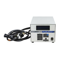
Unitek HF2S/460 User Manual (70 pages)
2 kHz HIGH FREQUENCY RESISTANCE WELDING POWER SUPPLY
Brand:
Unitek
| Category:
Power Supply
| Size: 3.31 MB
Table of Contents
Table of Contents
4
Chapter 1: Description
9
Chapter 9: Rs-485 Datacom
9
Chapter 2: General Set-Up
11
Required Connections
11
Physical Space Requirements
11
HF2 Weld Control Dimensions
11
HF2 Weld Transformer Dimensions
11
Power Line Voltage, Current, and Wire Size Requirements
12
Insulation Requirements
12
Power Line Fuse Requirements
12
HF2 Weld Transformer Electrical Specifications
13
HF2 Welding System Maximum Secondary Loop Resistance
14
HF2 Maximum Secondary Loop Resistance Measurement
14
HF2 Weld Control to HF2 Weld Transformer Connections
14
HF2 Weld Transformer to Weld Head Connections
15
Weld Sentry Option
15
Help Screen Languages
15
Chapter 3: Welding System Set-Up
17
Welding System Set-Up Guide
17
General Programming Instructions
17
Weld Head Set-Up
18
Firing Switch Cable Connection
18
Quick Start Programming Guide
18
Weld Head Set-Up
20
Firing Switch Cable Connection
20
Weld Head Valve Driver No. 1 Connection
20
Foot Switch Connection
20
Single Air Regulator Adjustment (Model 80 Series)
21
Dual Air Regulator Adjustments (Model 180 and Model 90 Series)
22
Quick Start Programming Guide
22
General Information
24
Weld Head Set-Up
24
CHAPTER 3: WELDING SYSTEM SET-UP (Continued)
24
Firing Switch Cable Connection
25
Foot Switch Connection
26
Weld Head Valve Driver Connections
26
Dual Air Regulator Adjustments
27
Quick Start Programming Guide
31
Electrical Connections
33
Non-Force Fired, Single Air or Cam Actuated Weld Head System
33
PLC Timing Diagram
34
Quick Start Programming Guide
34
Non-Force Fired, Multiple Air Actuated Weld Head System
36
Chapter 4: Controls
37
HF2 Weld Control - Front Panel
37
HF2 Weld Control - Rear Panel Inputs and Outputs
39
Power
39
Sensing Port
39
Sensing Port - Connector Pin Assignments
40
Output
40
Foot Switch Connector
41
Single-Level Foot Switch
41
Two-Level Foot Switch
41
Firing Switch Operation
42
Mechanical Firing Switch Cable
42
Optical Firing Switch Connector
42
Mechanical Firing Switch - 3-Wire Connection
42
Opto Coupler Firing Switch - 3-Wire Connection
43
Control Signals Connector
43
Control Signals - Pin Assignments
44
Control Signals - Remote Weld Schedule Selection Input
45
Control Signals - Emergency Stop Input
45
Control Signals - Process Inhibit Input
46
Control Signals - Output Relays
46
Relay K1
46
Relay K2
46
Accessory Port
46
Air Valve 1 and Air Valve 2 Driver Connectors
47
Air Valve 1 Driver
47
Air Valve 2 Driver
47
Chapter 5: Programming Modes
49
Help Screens
49
Machine States
49
Weld Graph Run State
49
Basic Weld Monitor Run State
50
Alphanumeric Run State
50
No Weld State
50
Standby State
50
Alarm State
51
Fire State
51
Menu State
51
Program State
52
Weld Graph Program State
52
Alphanumeric Program State
53
Output Relays
54
Relay 1 - Dual Air Head Operation
55
Chapter 6 : Advanced Welding Functions
57
Weld Functions
57
Basic Weld
58
Weld / Repeat
59
Quench/Temper
61
Pre/Postheat
62
Up/Down Slope
63
Braze
64
Rollspot
66
Seam
66
Dual Pulse
68
Pulsation
69
Advertisement
Advertisement
Related Products
Unitek HF2/380
Unitek HF2/460
Unitek HF2S/230
Unitek HF2S/380
Unitek HF2/208
Unitek HF2S/208
Unitek HF2/230
Unitek Watchman H3008
Unitek Watchman H3004
Unitek Watchman H3016
Unitek Categories
DC Drives
Battery Charger
Amplifier
Card Reader
UPS
More Unitek Manuals
Login
Sign In
OR
Sign in with Facebook
Sign in with Google
Upload manual
Upload from disk
Upload from URL