Table of Contents
Advertisement
Quick Links
Advertisement
Table of Contents

Related Manuals for Unitek UNIBOND 2


Summary of Contents for Unitek UNIBOND 2
- Page 1 Artisan Technology Group is your source for quality new and certified-used/pre-owned equipment SERVICE CENTER REPAIRS WE BUY USED EQUIPMENT • FAST SHIPPING AND DELIVERY Experienced engineers and technicians on staff Sell your excess, underutilized, and idle used equipment at our full-service, in-house repair center We also offer credit for buy-backs and trade-ins •...
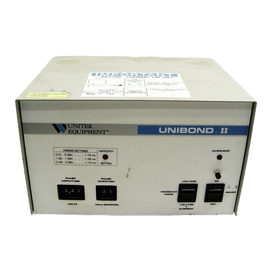
- Page 2 USERS'S MANUAL No. 990-1-050 ‘ ® E Q U I P M E N T I N C . UNIBOND II Constant Power/Constant Voltage Power Supply And Meter Accessory LINII'FIC. U N I B O N D - 0 , 0 40 too"...
-
Page 3: Table Of Contents
(F) Representations and warranties made by any person, including representatives of UNITEK EQUIPMENT, which arc inconsistent or in conflict with the terms of this warranty, including but not limited to the limitation of the liability of UNITEK EQUIPMENT as set forth above, shall not be binding upon UNITEK EQUIPMENT unless reduced to writing and signed by an Officer of UNITEK EQUIPMENT INC. - Page 4 Manual Part No. D a t e R e v Addendum Date REVISION RECORD -Date Basis-v evisio 16701 8/96 Correct the calibration procedure. Unitek Miyachi Corp. • 1820 S. Myrtle Ave. • Monrovia • CA 91017 • (818) 303-5676 Page 1 of 2 ERRUB2WPD...
- Page 5 SELECT VOLTS M E A S U R E 016 - 022 3.99 170V ±5V 2.99 143V ±5V 2.00 115V ±5V 170V ±5V 1.99 120V ±5V 0.99 70V ±5V 0.00 Unitek Miyachi Corp. ■ 1820 S. Myrtle Ave. ■ Monrovia ■ CA 91017 ■ (818) 303-5676 Page 2 of 2 ERRUI32.wPO...
-
Page 6: Description
DESCRIPTION 1 . 0 0 . 1.01. F E AT U R E S - The Model UB2, Unibond I I Power Supply, S t o c k No. 1 - 1 9 1 - 0 1 , i s s p e c i f i c a l l y designed f o r use w i t h e i t h e r t h e U n i t e k Model 4 0 , 4 6 , 8 6 , 8 7 , 1 2 7 o r 147 P a r a l l e l -Gap Weld Heads. -
Page 7: Specifications
2 . 0 0 . S P E C I F I C AT I O W 2.01. FEEDBACK MODES - VOLTAGE o r VOLTAGE + CURRENT Feedback. DURATION 2.02. OUTPUT - AMPLITUDE milliseconds v o l t s ALLOWABLE 0.01 - 0 . - Page 8 THE UNIBOND I I I S USED I N THE VOLTAGE FEEDBACK MODE ITS OUTPUT WILL BE IDENTICAL TO THAT OF THE UNITEK UNIBOND I , Stock Numbers 01-124-01 through 0 5 , AND OUTPUT TRANSFORMER, Stock Numbers 9-001-01 o r 10-105-01 through 0 4 , OPERATED I N THE MANUAL MODE.
- Page 9 WELDING RESISTANCE F i g u r e 4 r c 2 Rtb 1 t b 2 A r I Z r i F i g u r e 4 s h o w s t h e m e c h a n i c a l a n d e l e c t r i c a l e q u i v a l e n t s o f a t y p i c a l w e l d . The e l e c t r o d e f o r c e i s r e l a t i v e l y l o w s o t h a t t h e c o n t a c t r e s i s t a n c e b e t w e e n t h e e l e c - t r o d e s a n d t h e r i b b o n , R 1 a n d R c 2 ' r e m a i n s h i g h w i t h r e s p e c t t o t h e r e s i s t a n c e o f t h e w o r k p i e c e s , R t a n d R b .
- Page 10 Power = V o l t a g e x C u r r e n t = ( V o l t a g e ) 2 / R e s i s t a n c e Te m p e r a t u r e = k x E n e r g y = k x P o w e r x T i m e The E n e r g y d e l i v e r e d t o t h e w o r k p i e c e s i s i l l u s t r a t e d i n F i g u r e 5 c .
- Page 11 In a Constant Power System, F i g u r e 7 . t h e power w i l l remain constant r e g a r d - less o f what changes occur i n t h e welding r e s i s t a n c e . T h i s makes t h e process e a s i e r to c o n t r o l whenever: 1.
- Page 12 MIL LIO H M 2 . 1 7 . C O N T R O L S METER OVERLOAD IMPROPER S E T T I N G INDICATOR INDICATOR a t . • • • • • • • • • • • • 11 •...
- Page 13 2 . 1 7 . 4 . IMPROPER SETTING INDICATOR - W i l l i l l u m i n a t e whenever t h e combination o f Pulse Amplitude and Pulse Width a r e n o t w i t h i n t h e a l l o w a b l e s e t t i n g s a s shown i n 2.02.
- Page 14 2 . 2 0 . T Y P I C A L SYSTEMS BL Stereo Zoom Scope ..0 " ..00 ..1..F...°. 0 . , , , , , - .." ..• ... r e , 4.0.' „„.•...
-
Page 15: Machine Installation
Space deliberately left blank MACHINE INSTALLATION 3.01. T h e Unibond I I i s shipped i n a s i n g l e container which c o n t a i n s t h e C o n t r o l and t h e Output Transformer. -
Page 16: Electrode Installation And Maintenance
3 . 0 3 . C o n n e c t t h e Output Transformer t o t h e Unibond b y a t t a c h i n g t h e c a b l e from the Output Transformer t o t h e Transformer Output Connector l o c a t e d on t h e r e a r p a n e l . - Page 17 4.01 I N S T A L L A T I O N OF UNIBOND(R) ELECTRODES - MODELS 5OUB AND 8 6 4 . 0 1 . 1 . S e t t h e Weld Head F i r i n g Force t o t h e d e s i r e d v a l u e . U s e t h e D i r e c t Reading Force I n d i c a t o r o n t h e t o p o f t h e Model 8 6 Weld Head.
-
Page 18: Operation
4.03 I N S T A L L A T I O N OF UNITIP(TM) ELECTRODES - MODELS 5 0 AND 8 7 4 . 0 3 . 1 . O p e n t h e Electrode Clamping Thumbscrew on t h e Model 5 0 . S e t t h e Electrode Gap Adjustment Knob on t h e Model 8 7 f o r maximum gap w i d t h ( p a s t 3 5 ) . - Page 19 5.02. V A R I A B L E S FOR PARALLEL GAP WELDING 5 . 0 2 . 1 . G A P - The l a r g e r t h e distance between t h e e l e c t r o d e s . t h e Gap. t h e g r e a t e r the energy r e q u i r e d t o make a given bond.
- Page 20 5.05. F i g u r e 1 4 shows t h e v o l t a g e and c u r r e n t waveforms obtained from welding gold plated Kovar t o a n unplated copper t r a c e i n t h e Constant Vo l t a g e Mode u s i n g 35 o z Electrode Force.
- Page 21 Notice t h a t d u r i n g t h e f i r s t 1 ms t h e c u r r e n t increased t o 260 amps and t h e n decreased to 200 amps, p r i m a r i l y a s a r e s u l t o f t h e increased r e s i s t a n c e o f t h e molybdenum e l e c - trodes.
- Page 22 5 . 11 . F i g u r e 1 8 i l l u s t r a t e s t h e r e l a t i o n s h i p o f contact r e s i s t a n c e and e l e c t r o d e force.
- Page 23 VOLTAGE flowi••••••••••14 VOLTAGE volts/cm CURRENT amps/cm DURATION ms/cm CURRENT Figure 1 9 - Gold p l a t e d Kovar r i b b o n welded t o a n u n - plated, 1 o z copper t r a c e f o r 4 ms i n t h e Vo l t a g e Mode. VOLTAGE VOLTAGE VOLTAGE...
- Page 24 and t h e Amplitude increased t h e compensation d u r i n g t h e beginning o f t h e c y c l e . T h e disadvantage o f welding r e s i s t i v e m a t e r i a l s i n t h e Vo l t a g e + Current Mode i s t h a t t h e power does n o t decrease a s t h e m a t e r i a l s approach t h e i r m e l t i n g p o i n t a s i l l u s t r a t e d i n Figure 14b.
- Page 25 6.00. P R I N T E D _CIRCUIT WARD TRACE REPAIR 6.01. P a r a l l e l gap welding i s a s p e c i a l form o f s e r i e s welding i n which t h e s p a c - ing, u s u a l l y l e s s t h a n 0 .
-
Page 26: Printed Circuit Board Trace Repair
6 . 0 7 . T y p i c a l l y . 1 0 t o 3 0 ounces o f f o r c e i s r e q u i r e d on each e l e c t r o d e i n o r d e r t o weld a . - Page 27 6.11.07. I f you e l e c t t o use t h e Vo l t a g e + Current Mode, make t h e weld r e s i s t a n c e measurements o u t l i n e d i n 5 . 1 2 and 5 . 1 3 . S e t t h e Output Resistance Range S e l e c t o r and Control and switch t o t h e Vo l t a g e + Current Mode.
-
Page 28: Theory Of Operation
7 . 0 0 . T H E O R Y OF OPERATIOF 7 . 0 1 . I n r e s i s t a n c e s p o t welders. i t i s o f prime importance t o d e l i v e r t h e same amount o f energy t o each weld s i t e . - Page 29 oarFor era. b A 4 4 C - 1 1 F '56 E. CZ_ L C A D Z a S 1 r ( 4 1 # 4 . op Figure 25 - S i m p l e Vo l t a g e D i v i d e r i l l u s t r a t e s t h e P e r c e n t o f O u t p u t Power d e l i Ve r e d t o RL, t h e o u t p u t l o a d , when RL i s : ( a ) e q u a l t o Rout' •...
- Page 30 R88 i s t h e i n p u t r e s i s t o r t o t h e a m p l i f i e r a n d R132 and 8131 - R133 a r e r e s p e c t i v e l y the v o l t a g e and c u r r e n t feedback r e s i s t o r s .
- Page 31 Ro= RL E o , e o t R L R1.-1-Ro) SUBSTITUTING FOR R L = ° =A eo C o ( 2 R o f Figure 2 8 - When t h e output impedance o f an a m p l i f i e r e q u a l s t h e l o a d resistance, t h e output v o l t a g e w i l l b e o n e - h a l f t h e open c i r c u i t v o l t a g e .
-
Page 32: Calibration
8 . 0 0 . C A L I B R AT I O N 8.01. U n i t e k uses a s p e c i a l sample and hold technique t o p r e c i s e l y measure t h e pulse amplitudes and p u l s e d u r a t i o n s . - Page 33 8.04.02. S e t Pulse Amplitude t o 1 . 0 0 . T h e Improper S e t t i n g I n d i c a t o r should l i g h t . 8.04.03.
- Page 34 8 . 0 7 . 0 7 . When t h e Pulse Amplitude i s changed t o any v a l u e between 1 . 0 0 and 1 . 9 9 v o l t s , t h e p u l s e amplitude o f t h e d i s p l a y should b e w i t h i n 0 . 0 6 v o l t s o f t h e amplitude s e l e c t e d .
-
Page 35: Repair Service
8.10. C H E C K I N G RESISTANCE OF THE WELD HEAD 8.10.01. T h e r e s i s t a n c e o f t h e Weld Head can be measured. C o n n e c t i n g t h e Weld Head to t h e Unibond i n t h e u s u a l manner, s h o r t t h e Head b y i n s e r t i n g a s i n g l e RWMA-2 Electrode i n t o t h e Electrode Holders i n a manner which a l l o w s i t t o be f i r m l y clamped by both Holders. -
Page 36: Trouble-Shooting
10.00. A M B I A B - S H O O T I N O PROBLEM - Unibond does n o t work a t a l l and "Power On" l i g h t i s n o t i l l u m i n a t e d : SOLUTION # 1 : Check t h a t proper v o l t a g e i s a t o u t l e t and Unibond i s p r o p e r l y connected. - Page 37 ".: i 3.; - • ) PAZ • 1 . - e ; • e• 7 •._.-- . - - . . , _ _ • . . - 4 , . _ ' ' — l e • .r-71— 7 .
- Page 38 POWER S U P P LY PCB ASSEMBLY REAR PA N E L FRONT PANEL--▶, OUTPUT CABLE CONNECTOR Figure 33A - I n t e r n a l v i e w of Unibond I I . R i g h t S i d e View CONNECTORS Figure 33B - I n t e r n a l View o f Unibond I I .
- Page 39 Figure 3 4 - I n t e r n a l v i e w o f M i l l i o h m Meter R1 ( D R I V E A D J U S T ) R19 (CALIBRATION ADJUST) R6 ( L I M I T A D J U S T ) - 3 4 -...
- Page 40 Figure 3 5 - M i l l i o h m Meter P r i n t e d C i r c u i t Board FA R S 10E. P 1 4 4 30717 0 - + - 0 ^ R E V 9 40LES 2 .
- Page 42 11,00 P A R T S LIST (oontinued) ASSEMBL Y P A R T NO. N A M E REFERENCE DESIGNATOR(S) 8008 1020 1021 8052 R055 R089 R094 8095 4-30487-01 568-2-410 RESISTOR, CBN, 1 0 0 1 , 5%, 1/4W 8009 1010 562-2-121 RESISTOR, CBN, 1 .
-
Page 44: Schematics And Diagrams
Figure 36 - CONNECTION DIAGRAMS FOR ONIBOND I I 100 V, 6 0 - 6 0 HZ Z O A V , 0 0 6 O H L , T - .505 W O t A Y .01 I W O 2 A t , "... - Page 45 1 1 1 V I S I O N S A. 3r.T!:_•-• I J 4 - 3 0 4 ' 1 6 1 1 C O es • = 4 4 0 11•INA S Z t . Y 1.4,1/40 I01O1t 1.11511i M1111 I 1 1 4 7 1 ) , .
- Page 46 Figure 37 S C U M & T I C OP PULLIAM M I S R PCB 7 1 3 v fin ie 1 M A E S . 'ALTER P R AT E C T t o t r t UMIT HtriusT 1E5E2...
- Page 47 F i g u r e 3 8 ? I C O F O N : 1 3 0 1 0 ) I I FIRE r - 0 2 .._ , _ 1 1 . 1 P 1 1 t r z e t • , . . , ( •...
- Page 48 NMI I N N O M N M I M E I N N M I N I 111111 = I...
- Page 49 Artisan Technology Group is your source for quality new and certified-used/pre-owned equipment SERVICE CENTER REPAIRS WE BUY USED EQUIPMENT • FAST SHIPPING AND DELIVERY Experienced engineers and technicians on staff Sell your excess, underutilized, and idle used equipment at our full-service, in-house repair center We also offer credit for buy-backs and trade-ins •...
Need help?
Do you have a question about the UNIBOND 2 and is the answer not in the manual?
Questions and answers