Directed Electronics 4103, 4-button series Installation Manual
Keyless entry remote start 4-button series
Hide thumbs
Also See for 4103, 4-button series:
- Owner's manual (28 pages) ,
- Quick reference install manual (2 pages)
Table of Contents
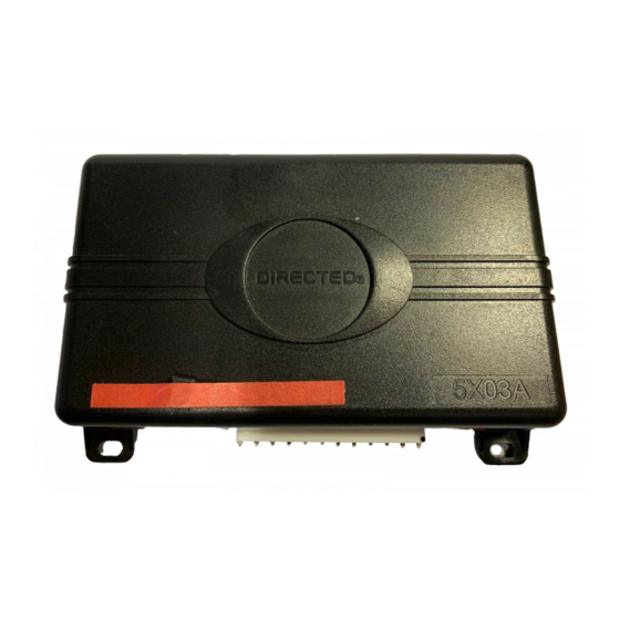
Advertisement
Installation Guide
Keyless Entry Remote Start
4103, 4-button series
This product is intended for installation by a professional
installer only! Attempts to install this product by a per-
son other than a trained professional may result in severe
damage to a vehicle's electrical system and components.
© 2012 Directed. Vista, CA
N4103 2012 01
Advertisement
Table of Contents

Subscribe to Our Youtube Channel
Related Manuals for Directed Electronics 4103, 4-button series


Summary of Contents for Directed Electronics 4103, 4-button series
- Page 1 Installation Guide Keyless Entry Remote Start 4103, 4-button series This product is intended for installation by a professional installer only! Attempts to install this product by a per- son other than a trained professional may result in severe damage to a vehicle’s electrical system and components.
- Page 2 Bitwriter®, Code Hopping™, Doubleguard®, ESP™, Fail- Safe®, Ghost Switch™, Learn Routine™, Nite-Lite®, Nuisance Prevention® Circuitry, Revenger®, Silent Mode™, Soft Chirp®, Stinger®, Valet®, Vehicle Recovery System®, VRS®, and Warn Away® are all Trademarks or Registered Trademarks of Direct- ed Electronics. Bitwriter (p/n ®...
-
Page 3: Table Of Contents
Contents Warning! Safety first ........................4 Wiring diagram ..........................5 Wiring connections ......................... 5 Main Harness (H1), 9-pin connector .................... 5 Door Lock - 3 pin connector ......................6 Heavy Gauge Relay (H2), 6-pin connector ................... 6 Satellite harness - 4-pin connector ....................6 Remote Start harness (H3) 5-pin connector ................... -
Page 4: Warning! Safety First
This testing should be performed by an authorized Directed Electronics dealer in accordance with the Safety Check outlined in this product installation guide. If the vehicle starts in gear, cease remote start operation immediately and consult with the user to fix the problem immediately. -
Page 5: Wiring Diagram
Wiring diagram Parking light jumpers Red 4-pin port, Bitwriter/ ESP2 or D2D Side View Antenna Side View LED (Programming indicator) Control Button (Valet Switch) Heavy Gauge Door Lock/unlock Relay Harness Antenna 4x03 Satellite Harness Primary Harness Remote Start Harness Wiring connections Main Harness (H1), 9-pin connector H1/1 LIGHT GREEN... -
Page 6: Door Lock - 3 Pin Connector
Door Lock - 3 pin connector LIGHT BLUE (-) UNLOCK EMPTY NOT USED GREEN (-) LOCK Heavy Gauge Relay (H2), 6-pin connector H2/1 PINK OUTPUT TO PRIMARY IGNITION CIRCUIT H2/2 PURPLE OUTPUT TO STARTER CIRCUIT ORANGE OUTPUT TO ACCESSORY CIRCUIT H2/3 H2/4 (+) 30A HIGH CURRENT 12V INPUT... -
Page 7: Tach Learning
Tach Learning To learn the tach signal: 1. Start the vehicle with the key. 2. Within 5 seconds, press and hold the Valet (Control) button. 3. After 3 seconds the system LED will light constant when the tach signal is learned. 4. -
Page 8: Neutral Safety Switch Interface
If the vehicle is not a General Motors product or a Dodge Dakota pickup, please call Directed Electronics Technical Support for an alternative shut-down method. Do not return the vehicle to the customer until this feature is properly installed! -
Page 9: Remote Start Shutdown Diagnostics
Remote start shutdown diagnostics If the remote start activates but fails to stay running, the remote start module has the ability to inform you of what may have caused the remote start failure. Before performing shutdown diagnostics it is important that you let the remote start shut off on its own i.e. -
Page 10: Programming System Features
Programming system features The System Features Learn Routine dictates how the unit operates. It is possible to access and change most of the feature settings using the Control button. 1. Turn the ignition on, then off. 2. Select a Menu. Press and hold the Valet button. The number of LED flashes and horn honks indicates the menu number. -
Page 11: Feature Menus
Feature menus Default settings are in bold type. Menu 1 Feature # Feature Opt. 1 Opt. 2 Opt. 3 Opt.4 Opt. 5+ Horn function Siren Siren Siren Siren 50 mS 20 mS 30 mS 40 mS Ignition con- trolled lock Ignition controlled unlock... - Page 12 6. Double Pulse Lock 1. Off: lock output pulses once 2. On: lock output pulses twice 7. Factory Alarm Disarm function 1. With Unlock: Factory Alarm Disarm wire pulses as programmed, at the same time as the unlock (Blue) wire, and when remote start is actiavted. 2.
-
Page 13: Menu 2
Menu 2 Feature # Feature Opt. 1 Opt. 2 Opt. 3 Opt.4 Opt. 5+ Engine check- Virtual voltage tachometer tach Engine 12 min 24 min 60 min Runtime Constant Park light Pulsed output Cranking 0.6 sec. 0.8 sec. 1.0 sec. 1.2 sec. -
Page 14: Red 4-Pin Port, Bitwriter/Esp2 Or D2D Programming
6. 2nd Ignition behavior 1. Ignition 2: the relay will emulate the Ignition 1 output during remote start. 2. Accessory 2: the relay will emulate the Accessory 1 output during remote start. 7. Accessory output 1. Off: the Accessory outputs will be OFF during diesel start delay. 2. -
Page 15: Bitwriter Only Options
Bitwriter only options If programming with the Bitwriter®, the learn routine can be locked or unlocked. If the learn routine has previously been locked, it must be unlocked with Bitwriter® - this cannot be done manually with the Valet button. The Bitwriter®... -
Page 16: Basic Remote Functions
Basic remote functions Button Function LOCK UNLOCK TRUNK RELEASE A U X REMOTE START A U X Note: See Owner's Guide for more details © 2012 Directed. All rights reserved. -
Page 17: Reset And Deletion
Reset and deletion If a feature/virtual tach needs to be reset or the remote controls need to be deleted, use the following proce- dure. 1. Turn the ignition to the ON position (The heavy gauge pink wire must be connected). 2. - Page 18 The remote start will activate, but the starter never engages. 1. Check for voltage on the purple starter wire two seconds after the remote start becomes active. If there is voltage present, skip to Step 5. If there is no voltage present, advance to Step 2. 2.
- Page 19 © 2012 Directed. All rights reserved.
- Page 20 The company behind this system is Directed Electronics Since its inception, Directed has had one purpose, to provide consum- ers with the finest vehicle security and car stereo products and acces- sories available. The recipient of nearly 100 patents and Innovation Awards in the field of advanced electronic technology.
Need help?
Do you have a question about the 4103, 4-button series and is the answer not in the manual?
Questions and answers