Table of Contents
Advertisement
Quick Links
Remote Car Starter Installation Manual for Model 40027, 40027T
Congratulations on your purchase of the AutoCommand
control from the comfort of your home or office in order to cool it down in the summer or heat it up in the winter.
®
AutoCommand
is for automatic transmission, fuel injected gasoline vehicles only. Please see pages 6-7 for important information about vehicles with
factory anti-theft systems. AutoCommand
• Will start your car by remote control, and run the heater,
defroster, or air conditioner to warm up or cool down the
car.
• Is designed to start the car if it is in park, and only if the
hood is closed.
• Has Lock, Unlock and Trunk Pop keyless entry features.
• Will attempt to start the car for up to six seconds, but no
longer (to avoid damage to the starter motor). Should the
car not start, or if it stalls after starting, the remote starter
will make two further attempts to start it.
Tools required to install the AutoCommand
Wire Cutters/Strippers
Soldering Iron
Pliers
Testmeter
We highly recommend that all connections be soldered for reliability.
Parts List included with the AutoCommand
Remote Starter Receiver Module
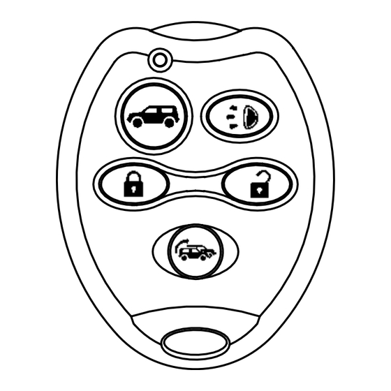
Transmitter
Antenna with Custom Clip
Control Harness (6 position)
Keyless Entry Harness (4 position)
6 Power & Ignition Wires
Yellow Headlight Wire
The following parts are included in the plastic bag:
Alcohol Pad
Alchohol
Pad
Green 30 A Fuse
On/Off Control Switch
Warning Label
2 Protected by
DesignTech Labels
© 2005 Directed Electronics, Inc.
www.designtech-intl.com • www.directed.com • 800-876-0800
PLEASE READ COMPLETELY BEFORE BEGINNING
®
Remote Car Starter. AutoCommand
®
is an extremely sophisticated system with multiple built-in safety and security features.
®
AutoCommand
®
Unit:
Electrical Tape
Screwdriver
Drill with
1
/
"and
5
/
"
4
16
drill bits
®
Unit:
Ring Terminal
Hood Pin Switch Set
2 Cable Ties
Yellow Butt Connector
®
Remote Car Starter allows you to start the car by remote
Remote Car Starter:
• Will not let the car be driven without the key in the
ignition.
• Shuts itself off automatically after 10 or 15 minutes
(programmable) if you forget to come out to your car.
• Will shut off if the brake pedal is pushed, the hood is
opened, or the transmission is shifted out of park - unless
the key is in the ignition and in the "run" position.
• Protects your vehicle with a basic alarm system.
• Is quality engineered and microprocessor controlled to
provide many years of reliable use.
• Comes with a Limited Lifetime Warranty.
Power Harness
Color
Pink
White
Yellow
Blue
Green
Black
Small Yellow
ON/OFF Switch Jack
Control Harness
Color
Function
Circuit Type
Green
Tach
(-) Input
Brown/White
Alarm Disarm
(–) 400 mA Output
W
hite/Black
IGN 3
(–) 400 mA Output
Green/White
Trunk
(-) 400 mA Output
Yellow/Red
Lock
(+/-) 400 mA Output
Color
Function
Circuit Type
White/Red
Unlock
(+/-) 400 mA Output
Gray/Black
Alarm Input
(-)
Input
Purple
Hood Switch
(-)
Input
Orange
Brake
(+)
Input
B l u e
Horn
(-) 400mA Output
* For free vehicle specific wire information, consult
our website at www.designtech-intl.com
1
Wiring Diagram
Circuit
Function
Type
Power (+12V) Input
Accessory
Relay output
Starter
Relay output
Ignition 1
Relay output
Ignition 2
Relay output
Ground
Input
HeaLights
Relayoutput
Coax
Antenna Jack
Required
No
Consult Wiring Guide*
Consult Wiring Guide*
No
No
Required
No
No
Yes
Yes
No
Required
Yes
Yes
Yes
Yes
Consult Wiring Guide*
Yes
Optional
v5.3 (40027)
Advertisement
Table of Contents

Related Manuals for Directed Electronics AutoCommand 40027


Summary of Contents for Directed Electronics AutoCommand 40027
-
Page 1: Wiring Diagram
Warning Label B l u e Horn (-) 400mA Output 2 Cable Ties * For free vehicle specific wire information, consult 2 Protected by Yellow Butt Connector our website at www.designtech-intl.com DesignTech Labels © 2005 Directed Electronics, Inc. v5.3 (40027) -
Page 2: Installation Instructions
How to share a hood pin you may wish to use the yellow butt connector, but we recommend solder- switch with an alarm ing. Wait to insert the 30 amp green fuse into the holder until step 11. v5.3 (40027) © 2005 Directed Electronics, Inc. -
Page 3: Optional Steps
After you have connected the GREEN wire, you need to teach the remote starter the vehicle’s tach rate at idle. Proceed to step 12B. Note: You must have already initialized the remote starter in Step 11. v5.3 (40027) © 2005 Directed Electronics, Inc. - Page 4 3 flashes No Tach or Stalled. Review Step 12 and make sure the no tach/tach wire option is programmed correctly. v5.3 (40027) © 2005 Directed Electronics, Inc.
- Page 5 Close the case and plug in all of the wire connectors. This option will unlock the door twice each time the unlock button on the The remote start module will turn OFF Ignition 2 while the starter is crank- ing. v5.3 (40027) © 2005 Directed Electronics, Inc.
-
Page 6: Special Cases
Transponder Volkswagen Passat 98+ Transponder GMC Jimmy 98+ Passlock II seconds between transmitters to begin teaching a new transmitter. GMC Safari 98+ Passlock II Volvo (all 98+) Transponder GMC Denali 99+ Passlock II v5.3 (40027) © 2005 Directed Electronics, Inc. - Page 7 Connect to the constant Ignition Key Sense (+) 12 volts Wire from Vehicle's Ignition Harness Connect to Purple Wire (hood pin switch) of the Remote Starter (Purple Wire must also connect to hood pin switch) v5.3 (40027) © 2005 Directed Electronics, Inc.
- Page 8 The company behind this system is Directed Electronics, Inc. Since its inception, Directed Electronics has had one purpose, to provide consumers with the finest vehicle security and car stereo products and accessories available. The recipient of nearly 100 patents and Innovations Awards in the field of advanced electronic technology, DIRECTED is ISO 9001 registered.
-
Page 11: Troubleshooting Guide
If you still get code 12, one of the toggle switch wires may have touched ground, possibly damaging the unit. Or maybe the switch was just turned off while it was running. Or maybe a defective switch? © 2005 Directed Electronics, Inc. Trouble Shooting v4-1... - Page 12 5 button remote, use the start button. (Refer to the installation manual for the complete control will lock the steps on how to make the unit enter the code learning process.) doors but will not unlock them. My 5 button remote will not control lock/unlock individually. © 2005 Directed Electronics, Inc. Trouble Shooting v4-1...
- Page 13 Likewise, if the vehicle requires a ground capable of more than 400ma you would need to use a relay. See Installation Note 111, Basic Uses of the Relay from our web site or our Fax On Demand. © 2005 Directed Electronics, Inc. Trouble Shooting v4-1...
- Page 14 Use the second marker to make a check when you have completed the step in the vehicle. This will help to make sure you have completed all steps, and that you have not missed any features the unit offers. © 2005 Directed Electronics, Inc. Trouble Shooting v4-1...
Need help?
Do you have a question about the AutoCommand 40027 and is the answer not in the manual?
Questions and answers