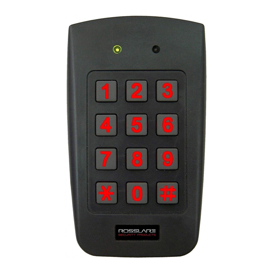
Rosslare AYC-F54 Instruction Manual
Backlit, waterproof convertible reader / controllers
Hide thumbs
Also See for AYC-F54:
- Instruction manual (60 pages) ,
- Installation and programming manual (62 pages)

Subscribe to Our Youtube Channel
Related Manuals for Rosslare AYC-F54


Summary of Contents for Rosslare AYC-F54
- Page 1 AYC-FGx4 Family Backlit, Waterproof Convertible Reader / Controllers Instruction Manual Models: AYC-F54 AYC-F64 AYC-G54 AYC-G64 August 2010...
-
Page 3: Table Of Contents
Table of Contents Table of Contents General Information ............4 Introduction ................4 Reader/Controller Types ............. 5 Box Content ................5 Ancillary Equipment ..............6 Technical Specifications ..........7 Key Features................8 Installation ..............10 Mounting the AYC-Fx4 and AYC-Gx4 ........10 Wiring Instructions ............ - Page 4 Table of Contents Request to Exit (REX) Function ..........32 Secure Application Appurtenances ........32 Programming the AYC-Fx4/AYC-Gx4 ........33 Programming Menu .................... 33 Entering Programming Mode ................34 Exiting Programming Mode................. 34 Changing Lock Strike Code ................34 Changing Auxiliary Code ..................35 Changing the Programming Code ..............
-
Page 5: General Information
If the unit is connected to a standard access control unit, then it functions as a reader. If the unit is connected to Rosslare's secure application appurtenances such as the PS-A25T, PS-C25T or PS-C25TU, it functions as a secured controller. -
Page 6: Reader/Controller Types
2X6 Mullion Upon power-on reset, the AYC-Fx4 / AYC-Gx4 searches for the presence of Rosslare's secure application appurtenances. If a secure application appurtenances is detected, then the AYC-Fx4 / AYC-Gx4 are automatically configured as a secure access control unit. This is indicated by two short beeps. If the secured controller is not detected, it is automatically configured as a reader, indicated by one short beep. -
Page 7: Ancillary Equipment
(power to lock) or fail secure (power to open) functions. Request to Exit (REX) button—normally open type. Switch is closed when pressed. Door monitor switch. Rosslare accessories can be found on www.rosslaresecurity.com. AYC-Fx4 and AYC-Gx4 family manual Page 6... -
Page 8: Technical Specifications
Technical Specifications Technical Specifications Specifications AYC-F54 AYC-F64 AYC-G54 AYC-G64 Electrical Characteristics Power supply type Linear type – recommended Operating voltage 5 - 16VDC (when used as a controller, provided by range the secure application appurtenance) Input current standby 75mA 105mA... -
Page 9: Key Features
(137x44x21 mm) Weight 0.474 lb (215g) 0.353 lb (160g) *Measured using Rosslare proximity card (AT-14) or equivalent. Range also depends on electrical environment and proximity to metal. Key Features The key features for the AYC-Fx4 and AYC-Gx4 series are: • Built-In Proximity Card Reader (125 KHz ASK Modulation) (for 64 series only) •... - Page 10 Technical Specifications Reader • Programmable keypad transmission format • LED control input • Programmable facility code • Programmable Proximity Card Transmission Format Clock & Data 26-Bit Wiegand Card + PIN Controller • Bi-directional secure communication with Rosslares’ secure application appurtenance •...
-
Page 11: Installation
Installation Installation Mounting the AYC-Fx4 and AYC-Gx4 Before starting, select the location to mount the AYC-Fx4 / AYC- Gx4. This location should be at shoulder height. Drill holes into the back of the unit according to how you want to mount the AYC- Fx4/AYC-Gx4. -
Page 12: Wiring Instructions
Wiring Instructions Wiring Instructions The unit is supplied with a 22-inch pigtail, having a 6-conductor cable. To connect the unit to the controller, perform the following: Prepare the unit's cable by cutting the cable jacket back 1¼ inches and strip the wire ½ inch. Prepare the controller cable by cutting the cable jacket back 1¼... - Page 13 Wiring Instructions Wiring diagram #1 (below) shows the wiring for the Controller Application using a Dual Relay Secure Application Appurtenance. Rosslare PS-X25 Figure 2 Controller Application Wiring Diagram #1 Wiring diagram #2 (below) shows the auxiliary output connection using internal power.
- Page 14 Wiring Instructions Wiring diagram #3 (below) shows the auxiliary output connection using the external power. Rosslare PS-X25 Figure 4 Controller Application Wiring Diagram #3 Figure 5: Reader Application Wiring Diagram #4 Page 13 AYC-Fx4 and AYC-Gx4 family manual...
-
Page 15: Reader Functionality
Reader Functionality Reader Functionality The AYC-Fx4/AYC-Gx4 series can function both as a reader and as a controller. If the unit is connected to standard access controller, it functions as a reader, indicated by one beep immediately after power-on reset. The following explains how the AYC-Fx4/AYC-Gx4 series functions as a reader. -
Page 16: Menu Description
Default Factory Settings are marked by a "*" sign. Menu Description Default Selecting Keypad Transmission Format Single Key, 6-Bit Wiegand (Rosslare Format) Single Key, 6-Bit Wiegand with Nibble + Parity Bits Single Key, 8-Bit Wiegand, Nibbles Complemented 4 Keys Binary + Facility Code, 26-Bit Wiegand... -
Page 17: Selecting Keypad Transmission Format
Reader Functionality green and the AYC-Fx4 / AYC-Gx4 will be in Programming Mode. Note: • The factory 4-digit Programming Code is 1234. • If a Programming Code is not entered within 30 seconds, the AYC-Fx4/AYC-Gx4 will return to Transmit Mode. Exiting Programming Mode 1) To exit the Programming Mode at any time press #: •... - Page 18 Keypad Transmission Format you wish to select Keypad Transmission Format Option Number Single Key, 6-Bit Wiegand (Rosslare Format) Single Key, 6-Bit Wiegand with Nibble + Parity Bits Single Key, 8-Bit Wiegand, Nibbles Complemented 4 Keys Binary + Facility Code, 26-Bit Wiegand...
-
Page 19: Single Key, 6-Bit Wiegand (Rosslare Format)
Reader Functionality Option 1: Single Key, 6-Bit Wiegand (Rosslare Format) Each key press immediately sends 4 bits with 2 parity bits added. Even parity for the first 3 bits and odd parity for the last 3 bits. 0= 1 1010 0 ="A" in Hexadecimal... -
Page 20: Keys Binary + Facility Code, 26-Bit Wiegand
Reader Functionality Option 4: 4 Keys Binary + Facility Code, 26-Bit Wiegand Buffers 4 keys and outputs keypad data with a three digit facility code like a standard 26-Bit card output. The facility code is set in Programming Menu number four and can be in the range 000 to 255. -
Page 21: To 5 Keys + Facility Code, 26-Bit Wiegand
Reader Functionality Option 5: 1 to 5 Keys + Facility Code, 26-Bit Wiegand Buffers up to 5 keys and outputs keypad data with a facility code like a 26-Bit card output. The facility code is set in Programming Menu number four and can be in the range 000 to 255. -
Page 22: Keys Bcd And Parity Bits, 26-Bit Wiegand
Reader Functionality Option 6: 6 Keys BCD and parity bits, 26-Bit Wiegand Sends buffer of 6 keys, adds parity and sends a 26-Bit Binary- Coded Decimal (BCD) message. Each key is a four bit equivalent of the decimal number. The keypad PIN code must be 6 key presses long. On the sixth key press of the 6 digit PIN code, the data is sent across the Wiegand Data lines as a BCD message. - Page 23 Reader Functionality The MD-P64 interface unit outputs the data received to 7 outputs emulating a keyboard. The interface unit will not affect any data that it receives from the proximity reader whether it is 26-Bit Wiegand or Clock & Data. Key pressed = ASCII Value 0 = '0' ( 0x30 hex ) 6 = '6' ( 0x36 hex )
-
Page 24: Selecting Proximity Card Transmission Format
Reader Functionality 5.2.2. Selecting Proximity Card Transmission Format The AYC-Fx4/AYC-Gx4 has three different proximity card formats to select from. Follow the steps below to select the appropriate Proximity Card reader transmission format that you wish to use. 1) Enter Programming Mode. Mode/Transmit Door/Program Green... -
Page 25: Changing The Programming Code
Reader Functionality seconds, the keypad will clear the card buffer and the PIN code entry buffer, generate a medium length beep and be ready to receive a new card. The keypad PIN code can be one to five digits long in the range of 0 to 99,999. -
Page 26: Changing The Facility Code
Reader Functionality • The Transmit LED will turn Door/Program Mode/Transmit red. Green 3) Enter the new 4 digit code you wish to set as the Programming Code ? ? ? 4) System returns to Transmit Mode • You will hear three beeps Door/Program Mode/Transmit •... -
Page 27: Return To Factory Default Settings
Reader Functionality 5.2.5. Return to Factory Default Settings Warning: You must be very careful before using this command! This will erase the entire memory and return all codes to their factory default setting. 1) Enter Programming Mode. Door/Program Mode/Transmit Green 2) Press “0”... -
Page 28: Controller Functionality
Controller Functionality Controller Functionality The AYC-Fx4/AYC-Gx4 series can function both as a reader and as a controller. If the unit is connected to Rosslares’ secure application appurtenance, it functions as a controller indicated by two beeps immediately after power-on reset. The lock strike output and Request to Exit input are not located on the AYC-Fx4/AYC-Gx4 unit, eliminating the possibility of unauthorized entry to the restricted area. -
Page 29: Normal User
Controller Functionality 6.1.1. Normal User A Normal User only has a Primary Code and is only granted access when the AYC-Fx4/AYC-Gx4 is in Normal or Bypass Mode. 6.1.2. Secure User A Secure User must have a Primary and Secondary Code programmed;... -
Page 30: Bypass Mode
Controller Functionality 6.2.2. Bypass Mode Door/Program Mode/Transmit MODE LED is orange Orange In Bypass Mode, access to the premises is dependent on whether the controller's Lock Strike Relay is programmed for Fail Safe Operation or Fail Secure Operation. When the Lock Strike is programmed for Fail Secure Operation, the door is locked until the "*"... - Page 31 Controller Functionality Changing from Secure Mode to Normal Mode The default factory setting for the Normal / Secure code is 3838. 1) Enter the Normal / Secure Door/Program Mode/Transmit code • Mode LED will flash green Mode/Transmit Door/Program Green 2) Press the “#” key to confirm the mode change.
-
Page 32: Auxiliary Input & Output
Controller Functionality Auxiliary Input & Output For optimum usability in different applications, the controller’s auxiliary input and output can be configured in ten different modes of operation. Door Alarms Door alarms can be generated by connecting the Auxiliary Input to a Door Position Switch. Either Door-Forced or Door-Ajar conditions are supported, as well as, a configurable delay timer for each alarm type. -
Page 33: Request To Exit (Rex) Function
REX Button has been released. Secure Application Appurtenances Rosslares’ secure application appurtenances are designed for use with Rosslare's secured series stand alone access control units, including AYC-FX4/AYC-GX4. It is designed to operate indoors and installed within the secured premises. The AYC-FX4/AYC-GX4 must be used with one of Rosslares’... -
Page 34: Programming The Ayc-Fx4/Ayc-Gx4
Controller Functionality Programming the AYC-Fx4/AYC-Gx4 Programming the AYC-Fx4/AYC-Gx4 is done solely via the unit's keypad driven Programming Menu System. To reach the Programming Menu System the AYC-Fx4/AYC-Gx4 must first be placed into Programming mode. See Entering Programming Mode on page 34 for more information. During the AYC-Fx4/AYC-Gx4 manufacturing process certain codes and settings are pre-programmed. -
Page 35: Entering Programming Mode
Controller Functionality 6.9.2. Entering Programming Mode 1) Press the # key twice within 2 seconds. • Mode LED will turn off. Door/Program Mode/Transmit • Door LED will turn red. 2) Enter your Programming Code ? ? ? • Door LED will turn green Door/Program Mode/Transmit Green... -
Page 36: Changing Auxiliary Code
Controller Functionality 2) Press “1” to enter Menu 1. • The Mode LED will turn Door/Program Mode/Transmit red. Green 3) Enter the new code you wish to set as the Lock Strike Code. 4) System returns to Normal Mode/Transmit Door/Program mode. -
Page 37: Changing The Programming Code
Controller Functionality 6.9.6. Changing the Programming Code 1) Enter Programming mode. Door/Program Mode/Transmit Green 2) Press “3” to enter Menu 3. • The Mode LED will turn Door/Program Mode/Transmit green. Green Green 3) Enter the new code you wish to set as Programming Code 4) System returns to Normal Door/Program... -
Page 38: Changing The Normal / Bypass Code And Door Chime Settings
Controller Functionality 6.9.8. Changing the Normal / Bypass Code and Door Chime Settings 1) Enter Programming mode. Mode/Transmit Door/Program Green 2) Press “5” to enter Menu 5 • The Mode LED will flash Mode/Transmit Door/Program orange. Orange Green 3) Hereafter, are four different ways to program the normal / bypass code and door chime. -
Page 39: Defining The Auxiliary Input And Output
Controller Functionality 3) Construct a code using instructions hereafter. ? ? ? First Digit For fail secure operation, the first digit is set to 0. For failsafe operation, the first digit is set to 1. Second Digit Siren Time in minutes (1-9, 0-disabled) Third and Fourth Digits Enter the number of seconds (from 1 to 99) that you want the Lock Strike to be released. - Page 40 Controller Functionality 3) Construct a code using the instructions below. 2 ? ? ? Auxiliary Mode Auxiliary Setting Auxiliary Mode In addition to the Lock Strike Relay and Lock Strike REX, the AYC-FX4/AYC-GX4 features an Auxiliary Input. The Auxiliary Mode defines the function of the Auxiliary Input.
-
Page 41: Quick Reference Guide For Auxiliary Mode Setting
Controller Functionality 6.9.11. Quick Reference Guide for Auxiliary Mode Setting Auxiliary Auxiliary Input Auxiliary Output Auxiliary Auxiliary Settings Mode Function Activated by Relay (in seconds) AUX REX Valid code or AUX REX N.O. 01 to 99 Aux. relay release time 00 Aux. -
Page 42: Detailed Reference Guide
Controller Functionality 6.9.12. Detailed Reference Guide The following are brief descriptions of each auxiliary mode. To implement the features of each mode, refer to Defining the Auxiliary Input and Output, page 38. Auxiliary Mode 0 Auxiliary input function: Activates the auxiliary output Auxiliary output activated by: Valid user code, Auxiliary code, Auxiliary input E.g. - Page 43 Controller Functionality Auxiliary Mode 2 Auxiliary input function: Toggles normal/secure modes Auxiliary output activated by: Asterisk Button (*) E.g. In auxiliary mode 2, the auxiliary relay can function as a general purpose time switch that can be activated when the Asterisk button (*) is depressed.
- Page 44 Controller Functionality auxiliary relay shunts the door sensor for the duration of the shunt time, as defined by the auxiliary setting. If the door is left open longer than the shunt time, an alarm will be triggered. Auxiliary Mode 5 Auxiliary input function: Door Monitor Auxiliary output activated by: Shunt (explanation below)
- Page 45 Controller Functionality Auxiliary Mode 7 Auxiliary input function: Door Monitor Auxiliary output activated by: Door Ajar (door held open) E.g. In auxiliary mode 7, the controller can trigger the auxiliary relay, if it detects that the door has been held open (ajar) too long.
-
Page 46: Setting The Lockout Feature
Controller Functionality Auxiliary Mode 9 Auxiliary input function: Red LED control Auxiliary output activated by: Valid user code, Auxiliary code E.g. In auxiliary mode 9, the controller can function as a two-door controller and also provide indicator functionality control. The auxiliary relay is connected to the lock on the second door. -
Page 47: Enrolling Primary And Secondary Codes
Controller Functionality 3) Construct a code using the following 4 ? ? ? instructions: Set the number of wrong code attempts, which will cause Lockout between 0 and 9 attempts. Sets the Duration of the lockout, between 00 and 99, the value is multiplied by ten, resulting in 0-990 seconds 6.9.14. - Page 48 Controller Functionality Enrolling Primary and Secondary Codes There are two methods to enroll Primary and Secondary codes, the Standard Method and the Code Search Method. • The Standard Method is mainly used when the User Slot number for the user you wish to program is known. You can program both Primary and Secondary Codes using the Standard method.
- Page 49 Controller Functionality • If the selected slot already has a Primary and Secondary Code, you will hear a Door/Program Mode/Transmit long beep and the Green controller will return to Normal Mode. 4) Enter the PIN Code you wish to assign as the Primary or Secondary Code for this slot number.
-
Page 50: Deleting Primary And Secondary Codes
Controller Functionality If the Primary Code entered is not valid, you will hear a long beep and the AYC-Fx4/AYC-Gx4 will continue to wait for a valid Primary Code. 5) Enter the Code to be used as the Secondary Code. If the Secondary Code is valid, the controller will beep three times and return to Normal Mode. - Page 51 Controller Functionality If the programming code is valid, three beeps will be heard and the controller will return to its normal mode. If the programming code is invalid, a long beep will be heard and the controller will return to its normal mode. Note: It is recommended that a record be kept of added and deleted users so that it will be easier to keep track of which...
-
Page 52: Relay Codes Assignment
Controller Functionality If the Programming Code is invalid, you will hear a long beep and the unit will return to Normal Mode. Note: It is recommended that a record be kept of added and deleted users so that it will be easier to keep track of which user slots are empty and which user slots are not. -
Page 53: Relay Code Assignment Using Search Method
Controller Functionality If the assignment code is valid, Mode/Transmit Door/Program the Mode indicator will stop Green Orange flashing. The controller is now waiting for another slot number. Depress the # key to move to the next slot or enter a new slot number. If you do not wish to continue, depress the # key twice and the controller will return to its normal mode. -
Page 54: Pin Code Length / Factory Default Settings
Controller Functionality 6.9.18. Pin Code Length / Factory Default Settings Warning: • You must be very careful before using this command! Changing the pin code length will also erase the entire memory contents, including all user and special codes, and return all codes to their factory-default settings 1) Enter the Programming Mode/Transmit... -
Page 55: Replacing A Lost Programming Code
Controller Functionality 6.9.19. Replacing a Lost Programming Code Note: • The AYC-Fx4/AYC-Gx4 must be in Normal mode, otherwise this will not work. Make sure that the Mode LED is green before proceeding. 1) Remove power from the Power Supply Unit. 2) Press the REX Button on the Power Supply Unit. -
Page 56: Appendix A. Limited Warranty
5 years (60 Months). Warranty Remedy Coverage In the event of a breach of warranty, ROSSLARE will credit Customer with the price of the Product paid by Customer, provided that the warranty claim is delivered to ROSSLARE by the Customer during the warranty period in accordance with the terms of this warranty. - Page 57 This warranty shall not extend to any ancillary equipment not furnished by ROSSLARE, which is attached to or used in conjunction with a Product, nor to any Product that is used with any ancillary equipment, which is not furnished by ROSSLARE.
-
Page 58: Appendix B. Technical Support
Technical Support Appendix B. Technical Support Asia Pacific, Middle East, Africa Rosslare Security Products Headquarters 905-912 Wing Fat Industrial Bldg, 12 Wang Tai Road, Kowloon Bay Hong Kong Tel: +852 2795-5630 Fax: +852 2795-1508 E-mail: support.apac@rosslaresecurity.com United States and Canada... - Page 60 www.rosslaresecurity.com...
Need help?
Do you have a question about the AYC-F54 and is the answer not in the manual?
Questions and answers
it won't stop beeping
The Rosslare AYC-F54 beeps every two seconds when it is in lockout mode. This occurs if several wrong codes are entered consecutively. During lockout, the controller keypad and reader are disabled, the Mode LED is off, and the Door LED flashes red.
This answer is automatically generated