Thermoheat KFA75L User's Manual And Operating Instructions

Thermoheat KFA75L User's Manual And Operating Instructions

Kerosene portable forced air heaters

Advertisement

INDOOR/OUTDOOR PRODUCTS
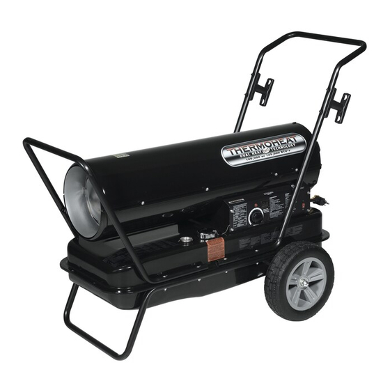
KEROSENE PORTABLE
FORCED AIR HEATERS
"USER'S MANUAL AND

OPERATING INSTRUCTIONS"

COMPLIES WITH UL733 AND
ANSI A10.10-1998
CAN/CSA/B140.0-03 AND CSA
B140.8-1967
MODEL : KFA75L, KFA125L, KFA210L
Before the first use of this heater, please read this USER'S MANUAL very
carefully. This USER'S MANUAL has been designed to instruct you as to
the proper manner in which to assemble, maintain, store, and most
importantly, how to operate the heater in a safe and efficient manner.
Please keep this manual for future reference.
CONSUMER : Retain this manual for future reference.
Questions, problems, missing parts? Before returning to your retailer, call our customer
service department at 877-447-4768 8:30 a.m. - 4:30 pm CST, Monday - Friday.
or email us at customerservice@ghpgroupinc.com

Advertisement

Table of Contents
loading
Need help?

Need help?

Do you have a question about the KFA75L and is the answer not in the manual?

Questions and answers

Subscribe to Our Youtube Channel

Summary of Contents for Thermoheat KFA75L

  • Page 1: Operating Instructions

    ANSI A10.10-1998 CAN/CSA/B140.0-03 AND CSA B140.8-1967 MODEL : KFA75L, KFA125L, KFA210L Before the first use of this heater, please read this USER’S MANUAL very carefully. This USER’S MANUAL has been designed to instruct you as to the proper manner in which to assemble, maintain, store, and most importantly, how to operate the heater in a safe and efficient manner.
  • Page 2 NEVER LEAVE THE HEATER UNATTENDED WHILE BURNING! DANGER: IMPROPER USE OF THIS HEATER CAN RESULT IN SERIOUS INJURY OR DEATH FROM BURNS, FIRE, EXPLOSION, ELECTRICAL SHOCK AND/OR CARBON MONOXIDE POISONING. WARNINGS: 1. RISK OF INDOOR AIR POLLUTION! • Use this heater only in well ventilated areas. Provide at least a three-square foot (2,800 sq. cm.) opening of fresh outside air for each 100,000 BTU/hr.
  • Page 3 Front Guard Hot Air Outlet Upper Shell Handle Fan Guard Lower Shell BTU Control Switch Fuel Tank Cord Wrap Side Cover Pressure Gauge Lamp Fuel Gauge Thermostot Knob Fuel Cap Power/Reset Switch Power Cord (Piggy Back) Figure 1. KFA75L MODEL...
  • Page 4 NEVER LEAVE THE HEATER UNATTENDED WHILE BURNING! Front Handle Rear Handle Upper Shell Hot Air Outlet Shell Lower Cord Wrap Fuel Gauge BTU Control Switch Fuel Cap Side Cover Pressure Gauge Lamp Fan Guard Thermostot Knob Room Temp. Display Power Cord Power/Reset Switch (Piggy Back) 10”...
  • Page 5: Unpacking And Assembly

    KFA125L KFA210L Wheel Support Frame Wheel Threaded Axle Front Handle Rear Handle Hardware kit : HW-KFA1001 Hardware kit : HW-KFA1016 Figure 4. KFA75L MODEL Hardware Kit Handle Cord Wraps HW-KFA1001 Figure 5. KFA125L/ KFA210L MODELS Screws Flange Screws Nuts Cap Nuts S...
  • Page 6 Front Guard Screw Handle ⅰ) Medium Phillips Screwdriver. ⅱ) 3/4 inch Socket or Adjustable Wrench Wedged Portion For KFA75L Model only Slit Hole (Assembly time for this product is 5 minutes) Tools Required Cord Wrap • Medium Phillips Screwdriver. 1) Lift front guard for arrow direction and Suppotor make sure that guard’s wedged portion...
  • Page 7 NEVER LEAVE THE HEATER UNATTENDED WHILE BURNING! Front Handle Screw Cap Nut S Rear Handle Hot Air Outlet Cord Wrap Flange Screw Fuel Tank Flange Air Inlet Wheel Support Frame Threaded Axle Wheel Wheel Bushing Cap Nut L Figure 7. Assembling Handles & Wheels CAUTION : DO NOT OPERATE heater without support frame assembled to tank.
  • Page 8 If this device activates and turns your heater off it may require service. Internal Shut-Off Temp. Reset Temperature MODELS Plus/Minus 10 Degrees Plus/Minus 10 Degrees KFA75L 176˚F/80˚C 122˚F/50˚C KFA125L 230˚F/110˚C 194˚F/90˚C KFA210L 194˚F/90˚C...
  • Page 9: Fueling Your Heater

    BTU control switch. BTU Control Switch BTU Control Switch Room Temp. Display Push to “HIGH” Lamp Lamp Push to “LOW” Thermostat Power/Reset Thermostat Power/Reset Switch Switch Control Knob Control Knob KFA75L Model KFA125L/210L Models Fan Guard Figure 8. Controls for All Models...
  • Page 10: Long Term Storage Of Your Heater

    IMPORTANT : Do not store kerosene over summer months for use during next heating season. Using old fuel could damage heater. 4. Reinstall fuel cap. Properly dispose of old and dirty fuel. (For KFA75L Model Only) 5. Reinstall fuel drain bolt to Fuel tank and tighten firmly using 3/4” socket or adjustable wrench.
  • Page 11: Maintenance

    NEVER LEAVE THE HEATER UNATTENDED WHILE BURNING! 9. MAINTENANCE WARNING!! : NEVER SERVICE HEATER WHILE IT IS PLUGGED IN OR WHILE HOT! USE ORIGINAL EQUIPMENT REPLACEMENT PARTS. Use of third party or other alternate components will void warranty and may cause unsafe operating conditions.
  • Page 12 NEVER LEAVE THE HEATER UNATTENDED WHILE BURNING! E.) NOZZLE REMOVE DIRT IN NOZZLE AS NEEDED (SEE PAGE 16). Combustion Chamber (For KFA75L/125L Models Only) Screw - Remove upper shell (See page 10). Ignitor Wire - Remove fan blade (See page 10).
  • Page 13: Spark Plug

    F.) SPARK PLUG Screw CLEAN AND REGAP EVERY 600 HOURS OPERATION OR REPLACE AS NEEDED. (For KFA75L/125L Models Only) - Remove upper shell (See page 10). Spark Plug - Remove fan (See page 10). - Remove ignitor wire from spark plug.
  • Page 14: Pump Pressure Adjustment

    - Pull fuel line off fuel filter neck. - Turn fuel filter 90˚ to counter clockwise and pull to remove (KFA75L Model only). - Turn fuel filter 90˚ to clockwise and pull to remove (KFA125L/210L Models only).
  • Page 15: Replacing Fuse

    NEVER LEAVE THE HEATER UNATTENDED WHILE BURNING! 10. REPLACING FUSE NOTICE : This heater is fuse protected. If your heater fails to ignite, DO NOT RETURN YOUR HEATER TO THE STORE. Please follow the simple instruction below to inspect and change the fuse. PROCEDURE FOR REPLACING FUSE WARNING : SHOCK HAZARD To prevent personal injury, unplug the power cord before replacing fuse.
  • Page 16: Troubleshooting

    NEVER LEAVE THE HEATER UNATTENDED WHILE BURNING! 11. TROUBLE SHOOTING GUIDE TROUBLE POSSIBLE CAUSE CORRECTIVE ACTION Heater ignites but MAIN PCB 1. Wrong pump pressure 1. See Pump Pressure Adjustment, assembly shuts heater off after Page 13. a short period of time. 2.
  • Page 17: Wiring Diagram

    NEVER LEAVE THE HEATER UNATTENDED WHILE BURNING! 12. WIRING DIAGRAM A) WIRING DIAGRAM (KFA75L/KFA125L) CONTROL PCB SPARK PLUG BLACK IGNITOR BLACK POWER LAMP (LED) ORANGE BLACK PUMP WHITE MOTOR CAPACITOR GREEN THERMOSTAT CN2(AC2)/ (TEMP. CONTROL) EARTH CN1(AC1)/ I/G WIRE MODEL...
  • Page 18: Specifications

    NEVER LEAVE THE HEATER UNATTENDED WHILE BURNING! 13. SPECIFICATIONS 32.0"(813mm) 11.7"(297mm) KFA75L Model KFA125L KFA210L 41.9"(1,063 ) 47.4"(1,205 ) 21.5"(547 ) 23.1"(587 ) 33.5"(850 ) 32.4"(824 ) KFA125L / KFA210L Models MODEL KFA75L KFA125L KFA210L HIGH 75,000 125,000 210,000 BTU/Hr.
  • Page 19 NEVER LEAVE THE HEATER UNATTENDED WHILE BURNING! 14. EXPLODED PARTS DRAWING (KFA75L/125L Models Only) NOTE : SPECIFY MODEL NUMBER AND PART NUMBER WHEN ORDERING PARTS. BURNER HEAD ASSEMBLY 21-3 21-8 21-5 21-7 21-2 21-1 21-4 21-6 21 22 MOTOR AND PUMP ASSEMBLY...
  • Page 20 NEVER LEAVE THE HEATER UNATTENDED WHILE BURNING! 15. PARTS LIST (KFA75L/125L Models Only) PART NO. Quantity KEY NO. DESCRIPTION KFA75L KFA125L Fuel Tank Assembly 2151-0027-00 2151-0028-00 Fuel Drain-Bolt 4329-0072-00 Fuel Gauge 2156-0049-00 2156-0050-00 Fuel Filter Assembly 2155-0005-00 2155-0001-00 Fuel Cap...
  • Page 21 NEVER LEAVE THE HEATER UNATTENDED WHILE BURNING! 15. PARTS LIST (KFA75L/125L Models Only) PART NO. Quantity KEY NO. DESCRIPTION KFA75L KFA125L 24-10 Insert See SP-KFA1000 See SP-KFA1000 24-11 End Pump Cover 3531-0027-00 3531-0027-00 24-12 Elbow 3231-0181-00 3231-0181-00 24-13 Lint Filter...
  • Page 22 NEVER LEAVE THE HEATER UNATTENDED WHILE BURNING! 14. EXPLODED PARTS DRAWING (KFA210L Model Only) NOTE : SPECIFY MODEL NUMBER AND PART NUMBER WHEN ORDERING PARTS. BURNER HEAD ASSEMBLY 21-8 21-3 21-7 21-1 21-5 21-2 21-4 21-6 23 13 MOTOR AND PUMP ASSEMBLY 24-2 24-5 24-6...
  • Page 23 NEVER LEAVE THE HEATER UNATTENDED WHILE BURNING! 15. PARTS LIST (KFA210L Model Only) PART NO. Quantity KEY NO. DESCRIPTION KFA210L Fuel Tank Assmebly 2151-0029-00 Fuel Drain-Bolt 4329-0072-00 Fuel Gauge 2156-0052-00 Fuel Filter Assmbly 2155-0001-00 Fuel Cap 2151-0003-00 Cord Bushing 3712-0013-00 Power Cord 3980-0087-00 Thermistor...
  • Page 24 NEVER LEAVE THE HEATER UNATTENDED WHILE BURNING! 15. PARTS LIST (KFA210L Model Only) PART NO. Quantity KEY NO. DESCRIPTION KFA210L 24-12 Elbow 3231-0181-00 24-13 Lint Filter See SP-KFA1005 24-14 Bolt Flange 4329-0016-00 24-15 Output Filter See SP-KFA1005 24-16 End Filter Cover 3221-0076-00 24-17 Ball...
  • Page 25 NEVER LEAVE THE HEATER UNATTENDED WHILE BURNING! 15. PARTS LIST (WHEELS AND HANDLE) 1) KFA75L MODEL PART NO. Quantity KEY NO. DESCRIPTION KFA75L Handle 3231-0073-00 Cord Wrap 3221-0041-00 Hardware Kit HW-KFA1001 2) KFA125L/210L MODELS PART NO. Quantity KEY NO. DESCRIPTION...

This manual is also suitable for:

Kfa125lKfa210l

Table of Contents

Save PDF