Table of Contents
Advertisement
GA-8I945P-G-RH
Intel
Pentium
®
®
User's Manual
Rev. 1002
12ME-8I945PGR-1002R
* The WEEE marking on the product indicates this product must not be disposed of with user's other household waste
and must be handed over to a designated collection point for the recycling of waste electrical and electronic equipment!!
* The WEEE marking applies only in European Union's member states.
D / Pentium
4 LGA775 Processor Motherboard
®
Advertisement
Table of Contents

Related Manuals for Gigabyte GA-8I945P-G-RH


Summary of Contents for Gigabyte GA-8I945P-G-RH
- Page 1 GA-8I945P-G-RH Intel Pentium D / Pentium 4 LGA775 Processor Motherboard ® ® ® User's Manual Rev. 1002 12ME-8I945PGR-1002R * The WEEE marking on the product indicates this product must not be disposed of with user's other household waste and must be handed over to a designated collection point for the recycling of waste electrical and electronic equipment!!
- Page 3 Copyright © 2005 GIGA-BYTE TECHNOLOGY CO., LTD. All rights reserved. The trademarks mentioned in the manual are legally registered to their respective companies. Notice The written content provided with this product is the property of Gigabyte. No part of this manual may be reproduced, copied, translated, or transmitted in any form or by any means without Gigabyte's prior written permission.
-
Page 4: Table Of Contents
Table of Contents GA-8I945P-G-RH Motherboard Layout ................. 6 Block Diagram ........................ 7 Chapter 1 Hardware Installation ..................9 Considerations Prior to Installation ..............9 Feature Summary ..................10 Installation of the CPU and Heatsink .............. 12 1-3-1 Installation of the CPU ..................12 1-3-2 Installation of the Heatsink .................. - Page 5 Chapter 3 Install Drivers ..................... 51 Install Chipset Drivers ..................51 Software Applications ..................52 Driver CD Information ..................52 Hardware Information ..................53 Contact Us ..................... 53 Chapter 4 Appendix ....................55 Unique Software Utilities ................55 4-1-1 EasyTune 5 Introduction ..................56 4-1-2 Xpress Recovery2 Introduction .................
-
Page 6: Ga-8I945P-G-Rh Motherboard Layout
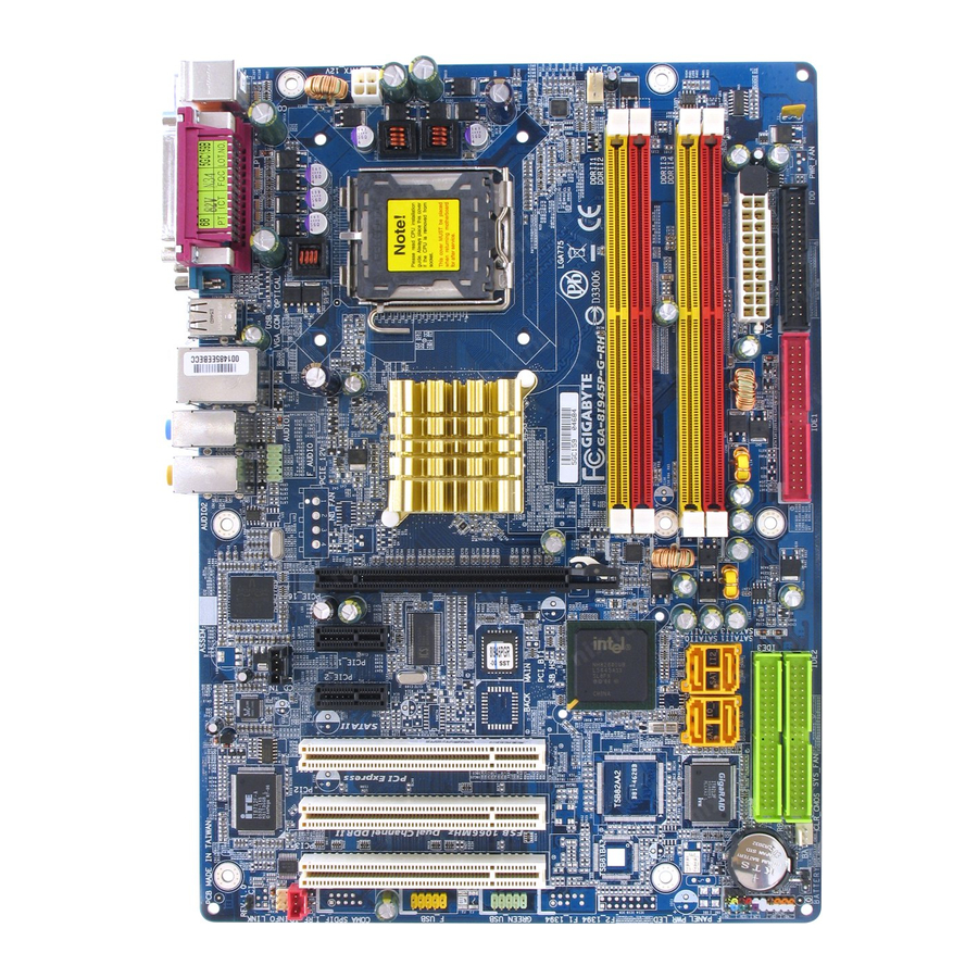
GA-8I945P-G-RH Motherboard Layout CPU_FAN KB_MS ATX_12V COAXIAL LGA775 OPTICAL AUDIO1 F_AUDIO Intel 945P AUDIO2 IDE1 PCIE_16 Broadcom 5789 PCIE_1 IDE3 IDE2 BIOS CD_IN ICH7 PCIE_2 CODEC PCI1 IT8712 PCI2 PCI3 F_USB GREEN_USB SPDIF_I F_PANEL RF_ID PWR_LED CLR_CMOS - 6 -... -
Page 7: Block Diagram
Block Diagram CPUCLK+/-(133/200/266MHz) LGA775 PCI-ECLK Processor (100MHz) Host Interface DDRII 667 /533/400MHz DIMM (Note) Intel PCI Express x16 945P Dual Channel Memory MCHCLK (133/200/266MHz) 2 PCI Express x1 RJ45 66MHz 33MHz Broadcom 14.318MHz PCI-ECLK 48MHz 5789 (100MHz) BIOS 4 SATA 3Gb/s PCI Express Bus Intel ATA33/66/100... - Page 8 - 8 -...
-
Page 9: Chapter 1 Hardware Installation
Chapter 1 Hardware Installation Considerations Prior to Installation Preparing Your Computer The motherboard contains numerous delicate electronic circuits and components which can become damaged as a result of electrostatic discharge (ESD). Thus, prior to installation, please follow the instructions below: 1. -
Page 10: Feature Summary
For example, 4 GB of memory size will instead be shown as 3.xxGB memory during system startup. (Note 3) To use a DDRII 667 memory module on the motherboard, you must install an 800/1066MHz FSB processor . (Note 4) Only supports ATAPI mode for HDD. GA-8I945P-G-RH Motherboard - 10 -... - Page 11 Onboard Audio ALC882 CODEC High Definition Audio Supports 2 / 4 / 6 / 8 channel audio Supports Line In ; Line Out (Front Speaker Out) ; MIC ; Surround Speaker Out (Rear Speaker Out) ; Center/Subwoofer Speaker Out ; Side Speaker Out connection SPDIF In connection SPDIF Out connection (coaxial+optical)
-
Page 12: Installation Of The Cpu And Heatsink
(Grasping the CPU firmly between your thumb and forefinger, carefully place it into the socket in a straight and downwards motion. Avoid twisting or bending motions that might cause damage to the CPU during installation.) GA-8I945P-G-RH Motherboard - 12 -... -
Page 13: Installation Of The Heatsink
1-3-2 Installation of the Heatsink Male Push Pin The top of Female Push Pin Female Push Pin Fig.1 Fig. 2 Please apply an even layer of heatsink paste on (Turning the push pin along the direction of arrow is the surface of the installed CPU. to remove the heatsink, on the contrary, is to install.) Please note the direction of arrow sign on the male push pin doesn't face inwards before installation. -
Page 14: Installation Of Memory
DIMM socket. Then push it down. Fig.2 Close the plastic clip at both edges of the DIMM sockets to lock the DIMM module. Reverse the installation steps when you wish to remove the DIMM module. GA-8I945P-G-RH Motherboard - 14 -... -
Page 15: Dual Channel Memory Configuration
GA-8I945P-G-RH supports the Dual Channel Technology. After operating the Dual Channel Technology, the bandwidth of Memory Bus will add double. GA-8I945P-G-RH includes 4 DIMM sockets, and each Channel has two DIMM sockets as following: Channel A : DDR II 1, DDR II 2... -
Page 16: Installation Of Expansion Cards
PCI Express x 16 slot. When you try uninstall the VGA card, please press the latch as the picture to the left shows to release the card. GA-8I945P-G-RH Motherboard - 16 -... -
Page 17: I/O Back Panel Introduction
I/O Back Panel Introduction PS/2 Keyboard and PS/2 Mouse Connector To install a PS/2 port keyboard and mouse, plug the mouse to the upper port (green) and the keyboard to the lower port (purple). LPT (Parallel Port) The parallel port allows connection of a printer, scanner and other peripheral devices. COAXIAL (SPDIF Out) The SPDIF coaxial output port is capable of providing digital audio to external speakers or •... -
Page 18: Connectors Introduction
Mic In jack ( ) . Please refer to the 2-/4-/6-/8- channel audio setup steps for detailed software configuration information. Connectors Introduction ATX_12V F_PANEL ATX (Power Connector) CD_IN CPU_FAN SPDIF_I SYS_FAN F_USB/GREEN_USB RF_ID IDE1/IDE2/IDE3 SATAII0 / SATAII1 / SATAII2 / SATAII3 CLR_CMOS F_AUDIO PWR_LED GA-8I945P-G-RH Motherboard - 18 -... - Page 19 1/2) ATX_12V/ATX (Power Connector) With the use of the power connector, the power supply can supply enough stable power to all the components on the motherboard. Before connecting the power connector, please make sure that all components and devices are properly installed. Align the power connector with its proper location on the motherboard and connect tightly.
- Page 20 The FDD connector is used to connect the FDD cable while the other end of the cable connects to the FDD drive. The types of FDD drives supported are: 360KB, 720KB, 1.2MB, 1.44MB and 2.88MB. Please connect the red power connector wire to the pin1 position. GA-8I945P-G-RH Motherboard - 20 -...
- Page 21 6) IDE1/IDE2/IDE3 (IDE Connector) An IDE device connects to the computer via an IDE connector. One IDE connector can connect to one IDE cable, and the single IDE cable can then connect to two IDE devices (hard drive or optical drive). If you wish to connect two IDE devices, please set the jumper on one IDE device as Master and the other as Slave (for information on settings, please refer to the instructions located on the IDE device).
-
Page 22: Front Audio Connector
9) PWR_LED PWR_LED is connected with the system power indicator to indicate whether the system is on/off. It will blink when the system enters suspend mode. Pin No. Definition MPD+ MPD- MPD- GA-8I945P-G-RH Motherboard - 22 -... -
Page 23: F_Panel (Front Panel Jumper)
10) F_PANEL (Front Panel Jumper) Please connect the power LED, PC speaker, reset switch and power switch etc of your chassis front panel to the F_PANEL connector according to the pin assignment below. Speaker Connector Message LED/ Power Power/ Switch Sleep LED Reset Switch IDE Hard Disk Active LED... - Page 24 SPDIF_IN connector. Check the pin assignment carefully while you connect the SPDIF cable, incorrect connection between the cable and connector will make the device unable to work or even damage it. For optional SPDIF cable, please contact your local dealer. Pin No. Definition Power SPDIFI GA-8I945P-G-RH Motherboard - 24 -...
- Page 25 13) F_USB/GREEN_ USB (Front USB Connector) Be careful with the polarity of the front USB connector. Check the pin assignments carefully while you connect the front USB cable, incorrect connection between the cable and connector will make the device unable to work or even damage it. For optional front USB cable, please contact your local dealer.
- Page 26 You may clear the CMOS data to its default values by this jumper. To clear CMOS, temporarily short 1-2 pin. Default doesn't include the "Shunter" to prevent from improper use this jumper. Open: Normal Short: Clear CMOS GA-8I945P-G-RH Motherboard - 26 -...
- Page 27 17) BAT(Battery) Danger of explosion if battery is incorrectly replaced. Replace only with the same or equivalent type recommended by the manufacturer. Dispose of used batteries according to the manufacturer's instructions. If you want to erase CMOS... 1. Turn OFF the computer and unplug the power cord. 2.
- Page 28 GA-8I945P-G-RH Motherboard - 28 -...
-
Page 29: Chapter 2 Bios Setup
Chapter 2 BIOS Setup BIOS (Basic Input and Output System) includes a CMOS SETUP utility which allows user to configure required settings or to activate certain system features. The CMOS SETUP saves the configuration in the CMOS SRAM of the motherboard. When the power is turned off, the battery on the motherboard supplies the necessary power to the CMOS SRAM. -
Page 30: The Main Menu (For Example: Bios Ver. : F1A)
If you can't find the setting you want, please press "Ctrl+F1" to search the advanced option hidden. Please Load Optimized Defaults in the BIOS when somehow the system works not stable as usual. This action makes the system reset to the default for stability. GA-8I945P-G-RH Motherboard - 30 -... - Page 31 Standard CMOS Features This setup page includes all the items in standard compatible BIOS. Advanced BIOS Features This setup page includes all the items of Award special enhanced features. Integrated Peripherals This setup page includes all onboard peripherals. Power Management Setup This setup page includes all the items of Green function features.
-
Page 32: Standard Cmos Features
Select this if no IDE devices are used and the system will skip the automatic detection step and allow for faster system start up. Access Mode Use this to set the access mode for the hard drive. The two options are: Large/Auto(default:Auto) GA-8I945P-G-RH Motherboard - 32 -... - Page 33 Capacity Capacity of currently installed hard disk. Cylinder Number of cylinders Head Number of heads Precomp Write precomp Landing Zone Landing zone Sector Number of sectors Drive A / Drive B The category identifies the types of floppy disk drive A or drive B that has been installed in the computer.
-
Page 34: Advanced Bios Features
If you want to cancel the setting of password, please just press ENTER to make [SETUP] empty. (Note) This item will show up when you install a processor which supports this function. GA-8I945P-G-RH Motherboard - 34 -... - Page 35 CPU Hyper-Threading Enabled Enable CPU Hyper Threading Feature. Please note that this feature is only working for operating system with multi processors mode supported. (Default value) Disabled Disables CPU Hyper Threading. Limit CPUID Max. to 3 Enabled Limit CPUID Maximum value to 3 when use older OS like NT4. Disabled Disable CPUID Limit for windows XP.
-
Page 36: Integrated Peripherals
SATA Port 1/3 Set to This value will auto make by the setting "On-Chip SATA Mode" and "PATA IDE Set to". If PATA IDE were set to Ch. 0 Master/Slave,this function will auto set to Ch. 1 Master/Slave. GA-8I945P-G-RH Motherboard - 36 -... - Page 37 USB Controller Enabled Enable USB Controller. (Default value) Disabled Disable USB Controller. USB 2.0 Controller Disable this function if you are not using onboard USB 2.0 feature. Enabled Enable USB 2.0 Controller. (Default value) Disabled Disable USB 2.0 Controller. USB Keyboard Support Enabled Enable USB Keyboard Support.
- Page 38 Using Parallel port as Extended Capabilities Port. ECP+EPP Using Parallel port as ECP & EPP mode. ECP Mode Use DMA Set ECP Mode Use DMA to 3. (Default value) Set ECP Mode Use DMA to 1. GA-8I945P-G-RH Motherboard - 38 -...
-
Page 39: Power Management Setup
Power Management Setup CMOS Setup Utility-Copyright (C) 1984-2005 Award Software Power Management Setup ACPI Suspend Type [S1(POS)] Item Help Soft-Off by PWR-BTTN [Instant-Off] Menu Level PME Event Wake Up [Enabled] Power On by Ring [Enabled] Resume by Alarm [Disabled] x Date (of Month) Alarm Everyday x Time (hh:mm:ss) Alarm 0 : 0 : 0... - Page 40 When AC-power back to the system, the system will be in "Off" state. (Default value) Full-On When AC-power back to the system, the system always in "On" state. Memory When AC-power back to the system, the system will return to the Last state before AC-power off. GA-8I945P-G-RH Motherboard - 40 -...
-
Page 41: Pnp/Pci Configurations
PnP/PCI Configurations CMOS Setup Utility-Copyright (C) 1984-2005 Award Software PnP/PCI Configurations PCI 1 IRQ Assignment [Auto] Item Help PCI 2 IRQ Assignment [Auto] Menu Level PCI 3 IRQ Assignment [Auto] : Move Enter: Select +/-/PU/PD: Value F10: Save ESC: Exit F1: General Help F5: Previous Values F6: Fail-Safe Defaults... -
Page 42: Pc Health Status
C / 194 Monitor CPU temperature at 90 C / 194 Disabled Disable this function. (Default value) CPU/SYSTEM FAN Fail Warning Disabled Disable the fan fail warning function. (Default value) Enabled Enable the fan fail warning function. GA-8I945P-G-RH Motherboard - 42 -... - Page 43 CPU Smart FAN Control Disabled Disable this function. Enabled When this function is enabled, CPU fan will run at different speed depending on CPU temperature. Users can adjust the fan speed with Easy Tune based on their requirements. (Default Value) CPU Smart FAN Mode This option is available only when CPU Smart FAN Control is enabled.
-
Page 44: Mb Intelligent Tweaker(M.i.t.)
Set C.I.A.2 to Sports. (Automatically increase CPU frequency(7%,9%) by CPU loading. Racing Set C.I.A.2 to Racing. (Automatically increase CPU frequency(9%,11%) by CPU loading. (Note) This item will show up when you install a processor which supports this function. GA-8I945P-G-RH Motherboard - 44 -... - Page 45 Turbo Set C.I.A.2 to Turbo. (Automatically increase CPU frequency(15%,17%) by CPU loading. Full Thrust Set C.I.A.2 to Full Thrust. (Automatically increase CPU frequency(17%, 19%) by CPU loading. Warning: Stability is highly dependent on system components. CPU Host Clock Control Please note that if your system is overclocked and cannot restart, please wait 20secs. for automatic system restart or clear the CMOS setup data and perform a safe restart.
- Page 46 Set FSB OverVoltage Control to +0.2V. +0.3V Set FSB OverVoltage Control to +0.3V. CPU Voltage Control Supports adjustable CPU Vcore from 0.8375V to 1.6000V. (Default value: Normal) Normal CPU Vcore Display your CPU Vcore Voltage. GA-8I945P-G-RH Motherboard - 46 -...
-
Page 47: Load Fail-Safe Defaults
Load Fail-Safe Defaults CMOS Setup Utility-Copyright (C) 1984-2005 Award Software Standard CMOS Features Load Fail-Safe Defaults Advanced BIOS Features Load Optimized Defaults Integrated Peripherals Set Supervisor Password Power Management Setup Set User Password Load Fail-Safe Defaults (Y/N)? N PnP/PCI Configurations Save &... -
Page 48: Set Supervisor/User Password
Setup Menu. If you select "Setup" at "Password Check" in Advance BIOS Features Menu, you will be prompted only when you try to enter Setup. GA-8I945P-G-RH Motherboard - 48 -... -
Page 49: Save & Exit Setup
2-11 Save & Exit Setup CMOS Setup Utility-Copyright (C) 1984-2005 Award Software Standard CMOS Features Load Fail-Safe Defaults Advanced BIOS Features Load Optimized Defaults Integrated Peripherals Set Supervisor Password Save to CMOS and EXIT (Y/N)? Y Power Management Setup Set User Password PnP/PCI Configurations Save &... - Page 50 GA-8I945P-G-RH Motherboard - 50 -...
-
Page 51: Chapter 3 Install Drivers
Chapter 3 Install Drivers Pictures below are shown in Windows XP. Insert the driver CD-title that came with your motherboard into your CD-ROM drive, the driver CD-title will auto start and show the installation guide. If not, please double click the CD-ROM device icon in "My computer", and execute the Run.exe. -
Page 52: Software Applications
This page displays all the tools that Gigabyte developed and some free software, you can choose anyone you want and press "install" to install them. Driver CD Information This page lists the contents of software and drivers in this CD-title. GA-8I945P-G-RH Motherboard - 52 -... -
Page 53: Hardware Information
Hardware Information This page lists all device you have for this motherboard. Contact Us Please see the last page for details. - 53 - Install Drivers... - Page 54 GA-8I945P-G-RH Motherboard - 54 -...
-
Page 55: Chapter 4 Appendix
Chapter 4 Appendix Unique Software Utilities (Not all model support these Unique Software Utilities, please check your MB features.) U-PLUS D.P.S. (Universal Plus Dual Power System) The U-Plus Dual Power System (U-Plus DPS) is a revolutionary eight-phase power circuit built for ultimate system protection. Designed to withstand varying current levels and changes, the U-Plus D.P.S. -
Page 56: Easytune 5 Introduction
Shows the current functions status GIGABYTE Logo Log on to GIGABYTE website Help button Display EasyTune 5 Help file Exit or Minimize button Quit or Minimize EasyTune 5 software (Note) EasyTune 5 functions may vary depending on different motherboards. GA-8I945P-G-RH Motherboard - 56 -... -
Page 57: Xpress Recovery2 Introduction
4-1-2 Xpress Recovery2 Introduction Xpress Recovery2 is designed to provide quick backup and restora- tion of hard disk data. Supporting Microsoft operating systems including Windows XP/2000/NT/98/Me and DOS, and file systems including FAT16, FAT32, and NTFS, Xpress Recovery2 is able to back up data on hard disks on PATA and SATA IDE controllers. - Page 58 (As this is a BIOS-related issue, it can be solved by BIOS update) GA-K8NXP-9 GA-8N-SLI Royal GA-K8U GA-K8N Ultra-9 GA-8N-SLI Pro GA-K8U-9 GA-8N-SLI GA-K8NF-9 (PCB Ver. 1.0) GA-K8NXP-SLI GA-K8NE (PCB Ver. 1.0) GA-K8N Ultra-SLI GA-K8NMF-9 GA-K8N Pro-SLI GA-8I945P-G-RH Motherboard - 58 -...
-
Page 59: Flash Bios Method Introduction
Please note that because updating BIOS has potential risk, please do it with caution!! We are sorry that Gigabyte Technology Co., Ltd is not responsible for damages of system because of incorrect manipulation of updating BIOS to avoid any claims from end-users. - Page 60 Contains the names of four tasks. Blocking a task and pressing Enter key on your keyboard to enable execu- tion of the task. Action bar: Contains the names of four actions needed to operate the Q-Flash/Dual BIOS utility. Pressing the buttons mentioned on your keyboards to perform these actions. GA-8I945P-G-RH Motherboard - 60 -...
- Page 61 Using the Q-Flash utility: This section tells you how to update BIOS using the Q-Flash utility. As described in the "Before you begin" section above, you must prepare a floppy disk having the BIOS file for your motherboard and insert it to your computer.
- Page 62 Primary Master : FUJITSU MPE3170AT ED-03-08 Primary Slave : None Secondary Master : CREATIVEDVD-RM DVD1242E BC101 Secondary Slave : None Press DEL to enter SETUP / Dual BIOS / Q-Flash / F9 For Xpress Recovery 09/23/2003-i875P-6A79BG03C-00 GA-8I945P-G-RH Motherboard - 62 -...
-
Page 63: Updating Bios With Q-Flash Utility On Single-Bios Motherboards
Press Del to enter BIOS menu after system reboots. When you are in BIOS menu, move to Load Fail-Safe Defaults item and press Enter to load BIOS Fail-Safe Defaults. Normally the system redetects all devices after BIOS has been upgraded. Therefore, we highly recommend reloading the BIOS defaults after BIOS has been upgraded. - Page 64 ESC:Reset F10:Power Off After BIOS file is read, you'll see a confirmation dialog box asking you "Are you sure to update BIOS?" Please do not take out the floppy disk when it begins flashing BIOS. GA-8I945P-G-RH Motherboard - 64 -...
- Page 65 Press Y button on your keyboard after you are sure to update BIOS. Then it will begin to update BIOS. The progress of updating BIOS will be shown at the same time. Q-Flash Utility V1.30 Flash Type/Size.........SST 49LF002A 256K Keep DMI Data Enable Do not turn off power or Updating BIOS Now...
-
Page 66: @Bios Utility
Please select "All Files" in dialog box while opening the old file. Please search for BIOS unzip file, downloading from internet or any other methods (such as: 8I945P Pro.F2a). Complete update process following the instruction. GA-8I945P-G-RH Motherboard - 66 -... - Page 67 III. Save BIOS In the very beginning, there is "Save Current BIOS" icon shown in dialog box. It means to save the current BIOS version. IV. Check out supported motherboard and Flash ROM: In the very beginning, there is "About this program" icon shown in dialog box. It can help you check out which kind of motherboard and which brand of Flash ROM are supported.
-
Page 68: 4- / 6- / 8- Channel Audio Function Introduction
Control Panel). Double-click the icon to open the Audio Control Panel. STEP 2: In the Audio Control Panel, click the Audio I/O tab. In the upper left list, click 2CH Speaker. GA-8I945P-G-RH Motherboard - 68 -... - Page 69 STEP 3: After a speaker or headphone is plugged into the rear Line Out jack, a small window will pop up and ask you what type of equipment is connected. Choose Headphone or Line Out depending on the device connected and click OK. The 2-channel audio setup is completed.
- Page 70 After installation of the audio driver, you should find an Audio Manager icon in your system tray (you can also find the icon in Control Panel). Double-click the icon to open the Audio Control Panel. GA-8I945P-G-RH Motherboard - 70 -...
- Page 71 STEP 2: In the Audio Control Panel, click the Audio I/O tab. In the upper left list, click 8CH Speaker. STEP 3: After plugging in 8-channel speakers to the rear speaker jacks, a small window will pop up and ask you what type of equipment is connected.
-
Page 72: Troubleshooting
6 beeps 8042 - gate A20 failure Continuous short beeps: Power error 7 beeps Processor exception interrupt error 8 beeps Display memory read/write failure 9 beeps ROM checksum error 10 beeps CMOS shutdown register read/write error 11 beeps Cache memory bad GA-8I945P-G-RH Motherboard - 72 -... - Page 73 - 73 - Appendix...
- Page 74 GA-8I945P-G-RH Motherboard - 74 -...
- Page 75 - 75 - Appendix...
- Page 76 GA-8I945P-G-RH Motherboard - 76 -...
- Page 77 - 77 - Appendix...
- Page 78 GA-8I945P-G-RH Motherboard - 78 -...
- Page 79 Contact Us Taiwan (Headquarters) Japan GIGA-BYTE TECHNOLOGY CO., LTD. NIPPON GIGA-BYTE CORPORATION Address: No.6, Bau Chiang Road, Hsin-Tien, Taipei 231, WEB address : http://www.gigabyte.co.jp Taiwan Singapore TEL: +886-2-8912-4888 GIGA-BYTE SINGAPORE PTE. LTD. FAX: +886-2-8912-4003 Tech. Support : Tech. Support : http://tw.giga-byte.com/TechSupport/ServiceCenter.htm http://tw.giga-byte.com/TechSupport/ServiceCenter.htm Non-Tech.
- Page 80 Shenyang CZECH REPUBLIC TEL: +86-24-23960918 Tech. Support : FAX: +86-24-23960918-809 http://tw.giga-byte.com/TechSupport/ServiceCenter.htm Australia Non-Tech. Support(Sales/Marketing) : GIGABYTE TECHNOLOGY PTY. LTD. http://ggts.gigabyte.com.tw/nontech.asp Tech. Support : WEB address: http://www.gigabyte.cz http://tw.giga-byte.com/TechSupport/ServiceCenter.htm Romania Non-Tech. Support(Sales/Marketing) : Representative Office Of GIGA-BYTE Technology Co., Ltd. in http://ggts.gigabyte.com.tw/nontech.asp Romania WEB address : http://www.giga-byte.com.au...
Need help?
Do you have a question about the GA-8I945P-G-RH and is the answer not in the manual?
Questions and answers