
Subscribe to Our Youtube Channel
Related Manuals for Meyra 2.263


Summary of Contents for Meyra 2.263
- Page 1 OPERATING MANUAL SCOOTER, MODEL 2.263 – 3-WHEEL MODEL 2.264 – 4-WHEEL We move people.
-
Page 2: Table Of Contents
Contents Foreword ....................... 6 Acceptance ....................6 Statutory regulations .................. 7 Legal requirements for Germany ................7 SCOOTER up to 6 km/h ...................7 SCOOTER more than 6 km/h ................7 CE regulations .......................8 Overview ....................... 9 Model: 2.264 ......................9 Control panel ......................10 Drive lock ......................11 Battery charging socket ..................11 Handling the SCOOTER ................ - Page 3 Selecting the operation ..................18 Adjusting the steering column ..............19 Switching on the SCOOTER ................19 Battery charge condition ................20 Recharging batteries ..................21 Charging procedure ..................22 Pre-operation checks ..................23 Battery capacity .....................23 Pre-selecting the maximum speed ...............24 Driving behaviour ....................25 Safety information ..................25 Accelerator lever ...................26 Travelling speed ....................26 Direction of travel ..................26...
- Page 4 Arm support ....................39 Swivelling up the arm support ..............39 Adjusting the angle of the arm support .............39 Adjusting the height of the arm supports ..........40 Adjusting the seat width over the arm supports ........40 Backrest ......................40 Front basket ......................41 Support castors ....................41 Removing support castors ................41 Attaching support castors ................41 Options ......................
- Page 5 Battery charger ....................49 Fuses/connections ....................50 Main fuse .......................50 Replace fuse ....................50 Lighting .......................51 Replacing defective filament bulbs .............51 Wheel change .....................55 Disassembling the drive wheels ..............55 Dismantling the steering wheels ..............56 Information for the authorised dealer .............57 Programming the driving behaviour ............57 Driving parameter ..................58 Standard programming ................58 Standard settings ..................58...
-
Page 6: Foreword
FOREWORD ACCEPTANCE We thank you for the confi dence you All products are checked for faults have placed in our company by way of in the factory and packed in special choosing the SCOOTER. boxes. The SCOOTER is a technical aid. It is ☞... -
Page 7: Statutory Regulations
SCOOTER up to 6 km/h STATUTORY REGULA- A liability insurance is only required TIONS for a SCOOTER over 6 km/h, but gen- erally recommendable. Please comply with the legal require- ments of the country in which the ☞ Electronic vehicles such as SCOOT- wheelchair is used. -
Page 8: Ce Regulations
Contact your insurance offi ce fi rst. CE regulations There you will receive an insurance ☞ Note: licence plate (moped plate), which is This vehicle corresponds to the re- to be attached to the rear panel with spective demands of the EC-direc- two screws. -
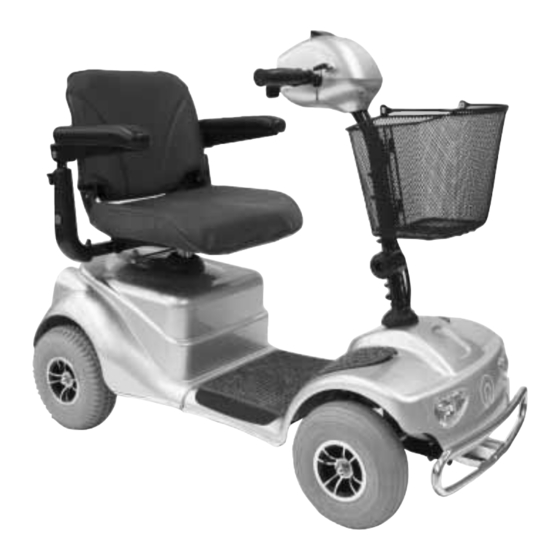
Page 9: Overview
OVERVIEW Model: 2.264 The overview shows the most important components and operating equip- ment. Pos. Description Pos. Description ➀ ➀ Seat Accelerator lever ➁ ➁ Handle bar grip Control panel ➂ ➂ Drive lock Locking screw - Angle of the steering column ➃... -
Page 10: Control Panel
Control panel (1) Battery capacity indicator (2) Indicator gauge of the pre-selected fi nal speed (3) Control display of the operational readiness / error display (status) (4) Plus-key – Rabbit (increases selectable speed) (5) Minus-key – Turtle (reduces the selectable top speed) (6) Key signal sound (7) Lights key (8) Indicator gauge for lighting... -
Page 11: Battery Charging Socket
Driving lock (1) Driving lock (2) Driving key position OFF (3) Driving key position ON Battery charging socket (4) Battery charging socket – The battery charging socket (4) is protected by a cover plate that can be swivelled to the side. -
Page 12: Handling The Scooter
High-frequency radiation HANDLING THE SCOOT- ▲ Mobile telephones should switched off during the use of the Attention: electric vehicle. – A mobile tel- Observe the safety information < ephone also transmits in standby Electronic wheelchairs >! mode, i.e. during the periods be- tween calls. -
Page 13: Tips For Accident Prevention
Tips for accident prevention First driving exercises A reduced maximum speed must be pre-selected on the control panel for the initial driving practice. Make your- self familiar with the driving behav- iour of the SCOOTER in small steps. The SCOOTER should not be used out- side of the familiar environment or on public highways until you have a safe control of the vehicle. -
Page 14: Safety Information
▲ Safety information Do not expose the SCOOTER to ex- treme weather conditions. ▲ Curves and slopes are to driven on ▲ Protect the upholstery with a cover with adequate speed. and/or park the SCOOTER in a pro- ▲ Danger of tilting in curves! tected area. -
Page 15: Control Panel
Control panel Pressure switches and symbols A key for activation of the function is Hazard warning fl asher key located under each symbol. – Switches the hazard warning fl ash- er on or off. – The indicator gauge lights up Plus-key (rabbit) when the warning lights are acti- –... -
Page 16: Drive Key
Drive key Position of drive key Position OFF The driving key is inserted horizontal- ly as far as possible in the driving key socket (1). – Turn the driving key from position < ON > as far as possible counter- clockwise (1). -
Page 17: Drive/Push Mode
Drive-/push mode ☞ Note: ☞ Switch the SCOOTER into the push mode only for manoeuvring on a level surface. Selecting the push mode In stillstand bring the driving key into the OFF position, then pull the key. ☞ The SCOOTER is now switched off. –... -
Page 18: Selecting The Operation
Selecting the operation Attention: The functions and safety of the SCOOTER must be checked before the start of each journey. Before fi rst operation the batteries should be charged through the charg- ing socket (1). ☞ Therefore observe chapter < Charg- ing batteries >. -
Page 19: Adjusting The Steering Column
Adjusting the steering column Loosen the hand wheel (1) to adjust the steering column. Attention: Hold onto the steering column with one hand at the handle bar in order to prevent it from uninten- tionally swivelling down. – Danger of injury! Retighten the hand wheel (1) when the desired position of the steering column is reached. -
Page 20: Battery Charge Condition
☞ Note: Do not move the acceleration lever (1) during the activation phase of about one second. – The electronic is ready for opera- tion when the indicator gauge for operational readiness (2) lights up constantly. Battery charge condition The battery indicator (3) displays the battery charge condition after the switch-on. -
Page 21: Recharging Batteries
Batteries should only be charged with Recharging batteries a battery charger that is suitable for The batteries should be charged im- the type and rating of the batteries. mediately after the daily use of the The guarantee is only preserved to SCOOTER in order to have the full its full extent when battery chargers driving distance available on the next... -
Page 22: Charging Procedure
Charging procedure To charge the batteries, fi rst switch off the SCOOTER and then plug the battery charger plug into the battery charging socket (1). Afterwards plug the mains plug of the battery charger into a corresponding outlet. The charging process is now started. -
Page 23: Pre-Operation Checks
Pre-operation checks ☞ Also view chapter < Maintenance instructions >. After the SCOOTER has been switched on, the battery indicator (1) displays the battery charge condition after the system test phase has ended. Battery capacity The number of lit LED’s reduces as the battery capacity reduces. -
Page 24: Pre-Selecting The Maximum Speed
Pre-selecting the maximum speed When activating the SCOOTER the last entered speed is pre-set. The fi nal speed is set (also while driv- ing) in 6 steps over the keys (1) and (3). The lit LED indicates the selected max- imum speed (2). -
Page 25: Driving Behaviour
Driving The speed is determined through movement of the accelerator lever (1) as well as the pre-selected fi nal speed. Attention: Drive especially carefully during the fi rst journeys! For this the pre-selectable speed is adjusted to the lowest level (sym- bol turtle). -
Page 26: Accelerator Lever
Accelerator lever The driving speed is determined while driving by the movement of the accel- eration lever (1) or (2). As soon as the acceleration lever is moved the SCOOTER, depending on the adjustment maximum fi nal speed, starts driving fast or slow. ☞... -
Page 27: Brakes
Brakes Emergency braking Let the driving actuator automatically Attention: spring back into the zero position. If the braking force reduces imme- – The SCOOTER brakes down at short- diately have the brakes repaired by est distance. a specialist workshop. • ☞... -
Page 28: Loading And Transportation
Loading and transportation Safety information For the transport in vehicles, you must get off the SCOOTER and sit in a suitable seat in the vehicle. Acci- dents and emergency braking result in forces which the SCOOTER was not designed to withstand and therefore greatly endanger a person sitting in the wheelchair. -
Page 29: Reducing The Size Of The Scooter
Reducing the size of the SCOOTER For storage or the transport (e.g. in a car), the size of the SCOOTER can be reduced as follows (1). 1. Switch off the SCOOTER and pull out the drive key. 2. Remove the front basket. 3. -
Page 30: Disassembling The Scooter
Disassembling the SCOOTER The SCOOTER can also be disassem- bled into several components as fol- lows for the transport in a small ve- hicle. (1) Front basket ☞ see section entitled < Front basket > (2) Seat ☞ see section entitled < Seat > (3) Rear revetment ☞... - Page 31 Removing the batteries 1. Switch off the SCOOTER and pull out the drive key. 2. Remove the seat (1). – For this activate the locking lever (2). 3. The ball grip of the selection le- ver has to be screwed off before removing the rear panelling is re- moved (3).
- Page 32 ☞ Left battery connection (1). ☞ Controller connection (2). ☞ Right battery connection (3). ☞ Note: The plugged connections are se- cured by spring locks that have to be unlocked by pressing the upper ends together. ☞ To pull them off hold onto the con- nection plugs.
- Page 33 Removing the drive unit 1. First pull out the locking bolt (1), the swivel the now unlocked drive from the front chassis. ☞ Note: For easier unlocking tilt the drive over the handle (2) slightly to the back. At the same time press the front chassis over the seat tube (3) slight- ly down and afterwards place it on the fl...
-
Page 34: Assembling The Scooter
Reassembly of SCOOTER-compo- nents ☞ Before assembly a visual check of the single components should be conducted for completeness and damages. Here the following is to be observed closely: – The brackets to receive the drive may not be bent. –... - Page 35 3. Replace the locking bolt (1). Attention: The locking bolt has to be visibly pushed through. Raising the steering column 1 . Loosen the hand wheel (2) to raise the steering column. ☞ Hereto observe chapter < Adjust- ment of the steering column >. Mounting the batteries Mounting is done in reverse order.
-
Page 36: Ramps And Lifting Platforms
Ramps and lifting equip- ment The SCOOTER can be loaded with the aid of ramps or lifting platforms. The following safety information must be observed: ▲ The safety information < Electronic wheelchairs >! ▲ The operating manual for the transport vehicle. ▲... -
Page 37: Special Safety Information
Special safety information Attention: ▲ For safety reasons, the SCOOTER The minimum load of ramps or lift- must be unloaded (without bag- ing equipment are to be read in gage and without user) during its the < Technical data > of the man- loading into a car or when a split ufacturer! ramp is used. -
Page 38: Components
COMPONENTS Seat ☞ Note: The seat supplied may vary from the one shown in the illustration. The seat (1) with padded arm supports is detachable and height-adjustable. Turning the seat The seat can be turned for an easier transfer to or from the seat. After activating the locking lever (2) the seat can be turned (3). -
Page 39: Adjusting The Seat Height
Adjusting the seat height The locking screw (1) of the seat pil- lar must be removed to adjust the seat height. The locking screw must be fi t- ted again after the positioning of the seat pillar (1). Arm support Attention: Do not carry the seat on the arm supports. -
Page 40: Adjusting The Height Of The Arm Supports
Adjusting the height of the arm supports The height of the arm supports can be steplessly adjusted after loosening the respective clamping screw (1). ☞ Maximally lift the arm support up- ward up to the marker. ☞ After height adjustment retighten the clamping screw (1). -
Page 41: Front Basket
Front basket The front basket can be lifted off up- wards (1). To replace the basket it is placed from the front onto the holder (2). Support wheels Removing support castors To remove the support castors remove the screwed connections (3) on one side fi... -
Page 42: Options
Strapping on the lap belt with OPTIONS lock Options are not a part of the standard ▲ Pull both belt halves to the front scope of supply. and slide the catch halves together ☞ so that they latch together. Then Note: carry out a pull test. -
Page 43: Maintenance
Tyres: SERVICE With different tyre pressure of the As any other technical product, the wheels of one axle the SCOOTER pulls SCOOTER also requires regular care to one side and the straight course is and maintenance. The following care restricted. A too low tyre pressure in- instructions and the maintenance creases the rolling resistance and more manual describe the measures that are... -
Page 44: Cleaning And Care
Cleaning and maintenance Plastic parts The plastic panels and parts are made ☞ Note: of high-quality plastic. ☞ Keep the lighting components ☞ Only clean the plastic parts with clean at all times and check for cor- warm water and neutral detergent rect functioning before each jour- or soft soap. -
Page 45: Disinfection
Disinfection Repairs Trustfully contact your local special- For disinfection you should use agents ist dealer of another specialist work- on a water basis such as Terralin, shop for carrying out repairs. They are Quartamon Med or Sagrotan Original briefed in carrying out the work and Concentrate. -
Page 46: Spare Parts
Spare parts Disposal ▲ Spare parts can only be ordered from The vehicle packing material can specialist dealers. In case of repair be disposed of as recyclable mate- work, only original spare parts are to rial. be used! ▲ The metal parts can be disposed of The spare parts list with the respective as recyclable scrap metal. -
Page 47: Batteries
Batteries Replacing the batteries The drive batteries are highly strained The SCOOTER requires special drive through the daily use of the SCOOTER batteries that are located within the and can only fulfi l their job when they battery pack. are cared for and charged. Batteries ☞... -
Page 48: Battery Instructions For Storage
▲ Battery instructions for storage Remove the battery pack fi rst, be- fore working on the electrical sys- Before storage, for example before a tem. winter pause, the following instruc- ▲ tions are to be observed: Never touch the battery poles with tools, cable ends or other metal ☞... -
Page 49: Battery Charger
Battery charger The SCOOTER requires a special charg- ☞ Only chargers suited for the SCOOTER may be used! ☞ Observe the operating manual of the charger! Technical requirements: for maintenance free, sealed batter- ies, – max. charging voltage: 29.5 V –... -
Page 50: Fuses/Connections
Fuses/connections Main fuse The mains fuse in located beneath the rear panel behind the batteries (1). ☞ Note: Have a burnt fuse replaced by a specialist workshop. Replace fuse Before replacing fuses, park the SCOOTER on a level surface and en- gage the brakes to prevent it from moving. -
Page 51: Lighting
Lighting ☞ Note: If a turn-signal bulb is defective, the remaining one blinks at double frequency. Replacing defective fi lament bulbs Switch off the SCOOTER before re- placing a defective bulb. ☞ Note: Hold onto the new bulb with a dry cloth. - Page 52 Front indicator Spherical bulb: 12V/5W W5W / KU E13 275 Removal: – Switch off the SCOOTER. – Pull the outer lamp socket (2) of the headlight (1) out of the hous- ing (3). – Pull the defective bulb out of the lamp socket.
- Page 53 Rear indicator Spherical bulb: 12V/10W BA15s Removal: – Switch off the SCOOTER. – Remove the seat and the rear cov- ☞ Therefore view chapter < Disas- sembling the scooter into its com- ponents – Removing the batteries >. – Turn the lamp socket of the defec- tive bulb and pull it from the hous- ing (1).
- Page 54 Back light Spherical bulb: 21/5W 12V BAY15D Removal: – Switch off the SCOOTER. – Remove the seat and the rear cov- ☞ Therefore view chapter < Disas- sembling the scooter into its com- ponents – Removing the batteries >. – Turn the lamp socket of the defec- tive bulb and pull it from the hous- ing (1).
-
Page 55: Wheel Change
Wheel change A wheel/tyre change requires tech- nical knowledge. You should there- fore have this work carried out by a specialist workshop. Sitting on the SCOOTER during a wheel change is not permitted. The SCOOTER must stand on a level and fi rm surface. Be- fore removing a wheel, safely prop up the chassis and prevent the SCOOTER from tipping or moving. -
Page 56: Dismantling The Steering Wheels
Dismantling the steering wheels Before replacement or repairs the protection cap has to be pulled off of the hexagon nut (1), then the steering wheel is to be disassembled by remov- ing the hexagon nut (1). ☞ Note: ☞ After attaching the steering wheel the hexagon nut (1) is to be screwed on tightly again. -
Page 57: Information For The Authorised Dealer
Information for the author- Programming the driving behav- iour ised dealer The driving behaviour of the SCOOT- A service manual containing a check ER can be adjusted through the pro- list for the annual inspection is avail- gramming device. able on request. ☞... -
Page 58: Driving Parameter
Driving parameter Standard settings By setting the parameters the driving The parameter values in the following characteristics of the SCOOTER are de- table are selected so that the inspec- fi ned. tion requirements of the CE certifi ca- tion are fulfi lled. Programming that ☞... -
Page 59: Maintenance
☞ Maintenance Note: Shorter intervals for brakes and The following maintenance Instruc- chassis checks are recommended in tions give you a guide for carrying out the case of severe operating con- the maintenance work. ditions, e.g. daily driving on up- hill/downhill gradients or use by a Attention: nursing service –... -
Page 60: Maintenance Instructions
Maintenance instructions WHEN WHAT Remark Carry out test yourself or Before starting out Test brakes for fault- with a helper. less operation Observe safety regula- Switch the selection le- tions < Electronic wheel- ver drive- / push mode chairs > chapter < Brakes to drive mode. - Page 61 Maintenance instructions WHEN WHAT Remark Do it yourself or with Every 2 weeks Check air pressure of the aid of a helper. Use the tyres (depending on distance a tyre gauge, if you do covered) Tyre pressure – view not have one, use the chapter <...
- Page 62 Maintenance instructions WHEN WHAT Remark Observe the chapter < Every 2 months Maintenance the bat- Batteries >. teries (or more frequently de- pending charging Sealed batteries: frequency and ambient – No maintenance temperature) Do it yourself or with the Every 6 months Check: aid of a helper.
-
Page 63: Fault Correction
Fault correction Fault Cause Remedy The battery indicator on Main fuse is defective. Have it repaired by a the control panel does specialist workshop. not light up after the switch-on. Indicator gauge for op- Malfunction in the elec- Have it repaired by a erational readiness (sta- tronics. -
Page 64: Technical Specifi Cations
The kilometric performance is greatly TECHNICAL DATA reduced by: Kilometric performance – frequent uphill driving, – poor battery charge condition, Kilometric performance depends to a large extent on the following factors: – low ambient temperature ( e . g . in winter) –... -
Page 65: Fuses
Fuses ☞ Therefore observe chapter < Fuses/connections >. Main fuse: ..................70 A Charging/control system fuse: ............10 A Lighting Headlight bulb: ......Spherical bulb 12V/5W W5W E13 Back light: ........Spherical bulb 21/5W 12V BAY15D Front indicator: ......Spherical bulb 12V/5W W5W E13 Rear indicator: .......Spherical bulb 12V/10W BA15S Tools The following tools are required for adjustments and maintenance:... -
Page 66: Stickers On The Scooter
Stickers on the SCOOTER Attention: Read the operating manuals and other provided documentation. Only switch to push mode on level surfaces. Position drive mode. Position push mode. Do not lift on the arm supports. Symbols The arrow with the hand shows to ar- eas where you should tough. -
Page 67: Scooter, Model 2.264
Scooter, model 2.264 All data within the following table relates to the standard version of the stated model. Dimensional tolerance ± 1.5 cm, ± 2 °. Model: ............Electronic-SCOOTER, model 2.264 Type plate: ..................at the seat brace Class of use as per DIN EN 12184: ..............Class B Electrical system: Drive control: .................. - Page 68 Range: – with 30 Ah – 5 h / 34 Ah – 20 h - batteries: ........up to 32 km Battery charger: for batteries from 24 Ah – 5 h / 28 Ah – 20 h ..........24 V / 6 A Performance: max.
-
Page 69: Inspection Certifi Cate
Inspection certifi cate Vehicle data: Model: Delivery note no.: Vehicle identifi cation No. Recommended safety inspection (at least every 12 months) Pre-delivery inspection Stamp of specialist dealer: Stamp of specialist dealer: Signature: Signature: Place, date: Place, date: Next safety inspection in 12 months Next safety inspection in 12 months Date: Date:... - Page 70 Recommended safety inspection Recommended safety inspection (at least every 12 months) (at least every 12 months) Stamp of specialist dealer: Stamp of specialist dealer: Signature: Signature: Place, date: Place, date: Next safety inspection in 12 months Next safety inspection in 12 months Date: Date: Recommended safety inspection...
-
Page 71: Notes
NOTES... - Page 72 NOTES...
- Page 73 NOTES...
-
Page 74: Guarantee
Guaranty is not granted for surface GUARANTEE damages, tyres of the wheels, dam- ages due to loosened screws or nuts We accept a guaranty for this prod- as well as worn out attachment holes uct according to the legal regulations. due to frequent assembly work. - Page 75 GUARANTEE COUPON Fill in the details! If necessary, copy and return. Guarantee Model designation: Delivery note no.: Vehicle ID No. (Fz-I-Nr.) (view type plate): Date of delivery: Stamp of the dealer:...
- Page 76 Your specialist dealer: MEYRA-ORTOPEDIA Vertriebsgesellschaft mbH Meyra-Ring 2 · D-32689 Kalletal-Kalldorf P.O. Box 1 703 • D-32591 Vlotho Fon +49 (0)5733 922-355 Fax +49 (0)5733 922-9355 info@meyra.de · www.meyra.de We move people. info@ortopedia.de · www.ortopedia.de 205 316 701 (Status: 2006-07) All technical modifi cations reserved!
Need help?
Do you have a question about the 2.263 and is the answer not in the manual?
Questions and answers