Advertisement
Quick Links
Advertisement

Subscribe to Our Youtube Channel
Related Manuals for Meyra Ortopedia Micro-electro-mobile 1.064


Summary of Contents for Meyra Ortopedia Micro-electro-mobile 1.064
- Page 1 Micro-electro-mobile Model 1.064 / 1.06424 Operating manual...
- Page 2 Contents Battery voltage Battery gauge Meaning of the applied markers Evaluation Introduction Preselectable maximum speed List of models Preselect the maximum speed Indications / contraindications Diving speed stages Acceptance Joystick Intended purpose Drive and steering movement Braking down the Micro-electro-mobile Adjustment Keys and symbols Statutory regulations...
- Page 3 Battery pack Repairs Repairs Retaining strap Customer Service Basket Spare parts Walking aid holder Information for extended pauses of use Seatlift Disposal Seat height adjustment Information for the specialist dealer Loading and transportation Programming the driving behaviour Loading Technical data Ramps and lifting platforms Tyre pressure of pneumatic tyres Transport of people inside a motor...
- Page 4 – Influence of impairing medications (ask website: your doctor or pharmacist). < www.meyra.com >. – Circumstances that prevent the individual ☞ Contact your specialist dealer when re- use of the control device. quired.
- Page 5 ACCEPTANCE – Sand and other dirt particles can seize on moving parts and render them without All products are checked for faults in the facto- function. ry and packed in special boxes. You must not let yourself be carried in your ☞...
- Page 6 STATUTORY REGULATIONS The Micro-electro-mobile is not licensed for use in public traffic. COMBINATION WITH MAN- UFACTURER FOREIGN PRODUCTS Any combination of your Micro-electro-mobile with components not supplied by us in general constitutes an amendment of your Micro-elec- tro-mobile. Please inquire with us if there is a valid combination clearance/release.
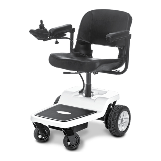
- Page 7 OVERVIEW Model: 1.064 / 1.06424 The overview shows the most important components and operating devices of the Mi- cro-electro-mobile. Pos. Description (1) Back support (2) Operating module (3) Clamping screw for operating module (4) Lever for seat locking device (5) Support castor (6) Selection lever drive-/push mode (7) Main fuse (8) Locking device of the arm support...
- Page 8 OVERVIEW Operating module The overview shows the operating controls of the operating module. Pos. Description (1) Operating module (2) Battery charging socket (3) Joystick (4) Reducing the adjusted speed preselection (5) Horn (6) Control display of the battery capacity and fault indicator (7) Switching the operating module on/off (8) Control display of the adjusted preselected...
- Page 9 BRAKES Releasing the brakes Only transfer into or out of the Micro-elec- Brake the Micro-electro-mobile down care- tro-mobile when the Micro-electro-mobile fully and in time. This is especially the case is switched off and the selection lever drive-/ when driving in front of people and while push mode is in drive mode! driving downhill! Inadvertently knocking the joystick will oth-...
- Page 10 Selecting the motor mode Battery voltage Activate the brakes [1 on page 38]. The battery indicator displays the battery volt- age after the system test performed by the ☞ Therefore observe chapter Locking the electronic system after the operating module brakes on page 9.
- Page 11 Preselectable maximum speed Danger of accident due to unsuitable setting of the preselected speed! After switching on the operating module, the maximum speed setting will be the same as that selected before switching off. Preselect the maximum speed By pressing the keys (6 on page 38) and (7 on page 38) the preselectable final speed can be decreased or increased.
- Page 12 Joystick Only move the joystick when the battery indicator (2) shows a constant light. Drive and steering movement The Micro-electro-mobile is accelerated and braked with the joystick (1). Move the joystick slowly in the desired driving direction. The further you move the joystick away from the centre position, the faster the Micro-elec- tro-mobile will travel (up to the preselected maximum speed).
- Page 13 Keys and symbols ON / OFF Switches the operating module on or off when pressing the key ☞ The electronic will conduct a system test when switched on. ☞ Do not motion the joystick during this time. Horn A signal sounds for as long as the key is pressed. Max.
- Page 14 SELECTING THE OPERATION PRE-OPERATION CHECKS Before starting to drive, the following should In order to obtain operational readiness of the be checked: Micro-electro-mobile the following directions The technical condition of the Micro-elec- are to be carried out in the indicated order. tro-mobile.
- Page 15 is not used for a long period of time. The Mi- ☞ The charging procedure only runs when cro-electro-mobile will then always be ready the lever of the mains fuse is set to < ON > for use. (13 on page 38). ☞...
- Page 16 The lithium-ion-batteries should be charged comfortably and safely steer the Mi- right after the daily use of the Micro-elec- cro-electro-mobile. tro-mobile so that the complete driving perfor- mance is available the next day. Removing the operating module To remove the operating module, slacken the Stillstand for more than one week clamping screw (14 on page 38).
- Page 17 ARM SUPPORTS Removing the seat Before removing the seat, the operating Swivel up the arm supports module needs to be taken off. – For this ob- The arm supports can be swivelled up for serve chapter Removing the operating module an easier transfer to/from the seat [24 on on page 16.
- Page 18 ☞ Therefore observe chapter Seat on To fasten the retaining strap, pull both ends page 16. forward and audibly let the buckle click into place. To open the retaining strap, press down Remove battery pack the release button and pull the two ends of the page 40].
- Page 19 ☞ Observe safety and general handling in- structions < Electric vehicles > chapter < Ramps and lifting platforms >. – This doc- ument and further information are availa- ble in the < Infozentrum > on our website < www.meyra.com >...
- Page 20 MAINTENANCE An incorrect or neglected cleaning and main- tenance of the Micro-electro-mobile results in a limitation of the product liability. Maintenance The following maintenance Instruction gives you a guide for carrying out the maintenance work. ☞ The maintenance schedule does not pro- vide information on the actual work re- quirement determined on the Micro-elec- tro-mobile.
- Page 21 MAINTENANCE SCHEDULE WHEN WHAT REMARK Every 6 -8 months Wheel attachments Do it yourself or with the aid of a (depending dis- helper. Wheel nuts or screws are tance covered) to be checked for tight fit. Securely tighten any loosened wheel nuts or screws and retight- en again after 10 operating hours or resp.
- Page 22 Tyres Tyres are made of a rubber mixture and can leave permanent or difficult-to-remove marks on some surfaces (e.g. plastic, wooden or par- quet flooring, carpets, mats). We cannot accept liabilty for damages on surfaces caused by wear or chemical processes of the tyres. Wheels Damaged wheels are to be replaced imme- diately through new wheels by a specialist...
- Page 23 Fault correction Fault Cause Remedy Battery indicator on the op- Main fuse has triggered. Set the lever of the main erating module does not fuse to < ON >. ☞ Lever of the main fuse is light up after the switch-on. In case of repeated trigger- set to <...
- Page 24 ERROR DIAGNOSTICS 2. Conduct the actions in column Remedy. Switch the operating module on. Errors, resp. information are shown through the battery gauge, the display of the maximum fi- ☞ For this observe chapter Switching the nal speed and the display of adjustment func- operating module on on page 10.
- Page 25 Fault Cause Remedy 7 blink impulses A system or joystick error. Do not touch the joystick dur- ing the initiation phase. – Switch the Micro-electro-mobile off and back on again. 8 blink impulses The operating module or the elec- Check cables and connecting tronic is defective or a system error plugs.
- Page 26 This safety information is an extract of the Safety and general handling instructions, that Accompanying person can be found on our website: < www.meyra. The accompanying person must be made com >. aware of all possible danger situation before Do not put your fingers into open frame the start of his/her supportive involvement.
- Page 27 Crossing obstacles Never lean towards the downhill direction when driving on rising, falling or transverse The ability to overcome obstacles is upon gradients. others dependent on the slope of the track. Avoid jerky changes of the driving condition Driving on stairs is forbidden! (especially with critically adjusted driving pa- Each crossing of obstacles involves a risk! rameters as for example high delay values).
- Page 28 The cushions and covers are normally fit with in the < Information center > on our website: care instructions (instruction for care). < www.meyra.com >. ☞ For this observe chapter Meaning of the symbols on the washing instruction on Finish page 33.
- Page 29 Disinfection Spare parts If the product is used by more than one person Safety relevant parts or assembly groups are (for example in a care centre), the use of a com- only to be assembled in a specialist work- mercial disinfectant is mandatory. shop.
- Page 30 DISPOSAL Programming the driving behaviour The driving behaviour of the Micro-electro-mo- bile can be adjusted through the programming device. ☞ Therefore observe the respective < Main- tenance and service manual >. The driving behaviour of the Micro-elec- tro-mobile should be adjusted to the individual requirements and the learning process of the The disposal must comply with the respective respective user at regular intervals.
- Page 31 Tyre pressure of pneumatic tyres – insufficient charging condition of the drive batteries, Maximum tyre pressure is printed on the tyres – low ambient temperature, on each side. – frequent starting and stopping, Full tyre pressure – steering wheel – aged drive batteries, Standard: –...
- Page 32 Values acc. to ISO 7176-15 for mod- Values acc. to ISO 7176-15 for mod- el 1.064/1.06424 el 1.064/1.06424 Range with lithi- Overall length 760 mm 760 mm – km 17 km um-ion-batteries Overall width 600 mm 700 mm Overall dimensions 170 kg 170 kg Further technical data for model...
- Page 33 Meaning of the symbols on the Further technical data for model washing instruction 1.064/1.06424 (the symbols correspond to European stand- ard) Ambient temperature Wash as delicates with the -25 °C to +50 °C (with lead batteries) indicated maximum tem- Ambient temperature perature in °C (with lithium-ion-bat- -20 °C to +60 °C...
- Page 34 Meaning of the labels on the Mi- Meaning of the symbols on the type cro-electro-mobile plate Attention! Read the operating Manufacturer manuals and other provided documen- tation. Order number Do not lift the Mi- cro-electro-mobile at the arm supports or Serial number leg supports.
- Page 35 We accept legal liability for this product within < Information center > sector < PMS > on our the scope of or general terms and conditions website < www.meyra.com >. and warranty and in certain cases other verbal We reserve the right to make technical im- resp.
- Page 36 INSPECTION CERTIFICATE Recommended safety inspection 1st year (at least every 12 months) Vehicle data: Stamp of specialist dealer: Model: Signature: Delivery note no.: Place, date: Serial-no.(SN): Next safety inspection in 12 months Date: Recommended safety inspection 3rd year Recommended safety inspection 2nd year (at least every 12 months) (at least every 12 months) Stamp of specialist dealer:...
- Page 37 Warrantee / Guarantee section Please fill out! Copy if necessary and send the copy to the specialist dealer. Warranty / Guarantee Model designation: Delivery note no.: SN (view type plate): Date of delivery: Stamp of the specialist dealer: Inspection certificate for transfer Vehicle data: Serial-no.(SN): Stamp of specialist dealer:...
- Page 42 NOTES...
- Page 43 NOTES...
- Page 44 Your specialist dealer MEYRA GmbH Meyra-Ring 2 32689 Kalletal Kalldorf GERMANY +49 5733 922 - 311 +49 5733 922 - 9311 info@meyra.de www.meyra.de 205 344 901 (Status: 2021-02) All technical modifications reserved. Original operating manual.
Need help?
Do you have a question about the Ortopedia Micro-electro-mobile 1.064 and is the answer not in the manual?
Questions and answers