Table of Contents
Advertisement
Quick Links
Advertisement
Table of Contents

Subscribe to Our Youtube Channel
Related Manuals for Meyra Ortopedia CL515


Summary of Contents for Meyra Ortopedia CL515
- Page 1 Scooter Model 1.274, CL515 Operating manual...
-
Page 2: Table Of Contents
Contents Brakes Service brake Meaning of the applied markers Braking down the scooter Introduction Parking brake List of models Releasing the parking brake in Indications / contraindications case of emergency Acceptance Hand brake Locking the hand brake Intended purpose Releasing the hand brakes Loosening the parking brake Adjustment Loosening the parking brake... - Page 3 Pre-operation checks Maintenance Battery charging condition Maintenance Recharging batteries Maintenance schedule Battery charging procedure Wheels Seat Fuses Replacing the fuses Turning the seat Fuse box Removing the seat Lighting Attaching the seat Headlights Adjustment of the seat height Fault correction Adjusting the distance seat to tiller Basic safety information Back support...
- Page 4 Technical data Tyre pressure of pneumatic tyres Maximum range Hill climbing ability Applied norms Values acc. to ISO 7176-15 for model 1.274, CL515 Further technical data for model 1.274, CL515 Meaning of the symbols on the washing instruction Meaning of the labels on the scooter Meaning of the symbols on the type plate Warranty / Guarantee...
-
Page 5: Meaning Of The Applied Markers
Safety instructions with a coloured back- out completely, please use our E-mail address ground are mandatory and need to be ob- < info@meyra.de > and inform the responsible served under any circumstance! governmental agency of your country. ☞ This symbol indicates tips and recommen- dations. -
Page 6: Acceptance
– Circumstances that prevent the individual The scooter is applicable on level, firm surfaces use of the control device. and can be used as follows: ☞ To these and other possible risk con- – outdoors (e.g. paved paths in parks). cerning your Scooter ask your doctor, –... -
Page 7: Combination With Manufacturer Foreign Products
LIFE SPAN dealer might need to conduct new conformity assessments and tests. We expect an average life span of about 5 years ☞ We recommend a regular control if the for this Scooter, as far as the Scooter is applied scooter adjustment in order to ensure a for its designated purpose and all maintenance long-term optimal provision even with... -
Page 8: Overview
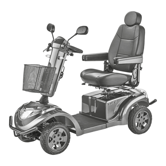
OVERVIEW Model: 1.274 The overview shows the most important components and operating devices of the Scooter. Pos. Description (15) LCD colour display (16) Hand brake lever (1) Head support (17) Indicator front right (2) Arm support (18) Connector socket for charging plug and (3) Steering column USB-plug (4) Bracket for front basket... -
Page 9: Lcd Colour Display
OVERVIEW LCD colour display The overview shows the display in the LCD col- our display. Pos. Description (1) Display of the time (2) Display of the preselected driving speed step (max. 6 steps) (3) Display of the bluetooth symbol with con- nected device (4) Display of the currently achieved driving speed... -
Page 10: Control Panel
OVERVIEW Control panel The overview shows the operating setting of the control panel with lighted pressure keys. Pos. Description (1) Lighting ON/OFF – Switches the scooter lighting on/off. ☞ View chapter Symbols of the LCD colour display on page 12. (2) Settings –... -
Page 11: Steering Column
OVERVIEW Steering column The overview shows the operating setting and components of the steering column. Pos. Description (1) Control panel (2) LCD colour display (3) Driving actuator for finger operation (4) Handle bar (5) Hand brake lever (6) Right indicator (7) Battery charging socket (8) Bracket for utensil basket (9) USB-charging socket... -
Page 12: Symbols Of The Lcd Colour Display
SYMBOLS OF THE LCD COLOUR DISPLAY Time Display of the current time. ☞ Depending on the set time in the adjustment screen. Bluetooth Blue display with active bluetooth connection. Final speed Display of the preselected final speed. ☞ With reducing speed, correspondingly less of the lighting segments are lit in the 6-step display. - Page 13 SYMBOLS OF THE LCD COLOUR DISPLAY Push mode The symbol lights up green when push mode is switched ☞ View chapter Selecting the push mode on page 17. Setting Time Displays the screen for setting the current time. ☞ View key setting in chapter Keys and symbol of the operating panel on page 14.
-
Page 14: Keys And Symbol Of The Operating Panel
KEYS AND SYMBOL OF THE OPERATING PANEL Plus key (rab- Increases the 6-step final speed by one step on each bit) pressure. ☞ For safety reasons we recommend to only press the < Plus-key > when the wheelchair is standing still. Minus key (tur- Decreases the 6-step final speed by one step on each tle) - Page 15 KEYS AND SYMBOL OF THE OPERATING PANEL Settings Opens the screen "Time". The hours and minutes are set by pressing the turn sig- nal and horn key left/right. With each pressing of the key the hour display increases. With each pressing of the key the hour display decreases. With each pressing of the key the minute display increas- With each pressing of the key the minute display de- creases.
-
Page 16: Handling Of The Scooter
HANDLING OF THE SCOOTER Parking brake The parking brake releases automatically dur- Short term parking of the scooter ing start-off. The scooter is to be secured as follows to pre- The parking brake is released by hand, through vent it from rolling off unintentionally: pressing the push mode key. -
Page 17: Releasing The Hand Brakes
Releasing the hand brakes Drive-/push mode Slightly pull the brake lever (1 on page 43). Only switch the scooter to push mode or push it when it is standing still for positioning – The locking button (2 on page 43) jumps out of the catch. -
Page 18: Radio Key
RADIO KEY STEERING COLUMN The LED (8 on page 43) is lit in blue as long Battery charging socket as the scooter is being used. Do not insert any objects other than the bat- Protect the radio key from getting damp or tery charging plug into the battery charging wet. -
Page 19: Battery Gauge
Battery gauge Each press of the key increases or decreases the selectable maximum final speed accord- The battery gauge (13 on page 43) displays ingly from slow (turtle symbol) to fast (rabbit the existing battery voltage as follows: symbol). The colours mean: Select a low maximum speed for driving situ- ations in which you do not feel confident/safe Green... -
Page 20: Left/Right Turns
Left/right turns ☞ The steering column is to be positioned so that the scooter can be steered In order to drive curves, move the steering col- comfortably and safely. umn to the right or left with the handles, de- pending on the desired curve radius. Switch on the Scooter. -
Page 21: Recharging Batteries
Recharging batteries the corresponding power socket. – The battery charging procedure is initiated. Solely use a charger that corresponds to the ☞ The charging procedure will only pro- type of battery! ceed with an intact battery fuse (25 on The batteries should be charged right after the page 45) as well as activated main use daily use of the scooter so that the complete (14 on page 44). -
Page 22: Attaching The Seat
Adjusting the arm support angle Attaching the seat The can of the arm support is continuously ad- Grab sideways under the seat surface in order justable by adjusting the stopper screw (36 on to lift the seat. page 46). After activating the locking lever (30 on page 45) the seat can be inserted into the Remove the arm support seat tube. -
Page 23: Front Basket
FRONT BASKET SUPPORT CASTORS With increasing weight inside the basket, the The support castors (45 on page 47) increase strength needed to steer increases. the stability against tipping over to the rear when crossing an obstacle or driving on a ris- Do not place valuable items such as wallets ing gradient. -
Page 24: Loading And Transportation
< www.meyra.com > in the < Down- ☞ Therefore view chapter Reducing the size of load Archive >. the scooter on page 24. -
Page 25: Transport Security
< Safety and gen- eral handling instructions electric vehicles > chapter < Transport in motor vehicles or with conveyors >. – This document and further information are available in the < Informa- tion center > on our website < www.meyra. com >. -
Page 26: Maintenance Schedule
Maintenance schedule WHEN WHAT REMARK Before starting out General Carry out test yourself or with a helper. Test for faultless operation. Checking the magnetic Carry out test yourself or brake with a helper. Switch the scooter on with If the scooter can be pushed, the radio key. - Page 27 Maintenance schedule WHEN WHAT REMARK Every 2 months Check the wheels Carry out a visual check (depending distance yourself or with a helper. covered) If the tyre profile is worn down or if the wheel is dam- aged, consult a specialist workshop for repairs.
-
Page 28: Wheels
Fuse box Wheels Have the cause f damage of a functional error Damaged wheels are to be replaced imme- repaired by a specialist dealer! diately through new wheels by a specialist dealer. Further flat fuses to secure the control system Tyres are made of a rubber mixture and and other power consumers are located in the can leave permanent or difficult-to-remove... -
Page 29: Fault Correction
Fault correction Fault Cause Remedy Battery LCD colour display Circuit breaker of the mains Switch the circuit breaker does not light up after the fuse is switched off or defec- switch-on. tive. If necessary have it repaired by the specialist workshop. Battery fuse defective. -
Page 30: Basic Safety Information
This safety information is an extract of the Transfer out of the Scooter Safety and general handling instructions, that can be found on our website: < www.meyra. Drive with the Scooter as closely as possible to the spot where you want to switch out of the com >. -
Page 31: Crossing Obstacles
Avoid driving on inclinations or slopes with in- The support castors can touch the ground sufficient surface condition. Even with only on while driving down, e.g. in front of the edge of sided existence of ice, water, moss or similar on an obstacle which can cause the drive wheels the ground, there is a danger that the Scoot- to lift off the ground. -
Page 32: Electrical System
Electrical system that the Scooter cannot slide away in case of an accident or sudden braking manoeu- An incorrect and/or inappropriate modifica- vre. tion of the driving behaviour can impair the – Additionally activate the handbrake. safety of the Scooter and the Scooter user. –... -
Page 33: Cleaning
Further information to cleaning can be found non-ionic tensides as well as solvents and es- in the < Information center > on our website: pecially alcohol. < www.meyra.com >. Do not clean the scooter with a high-pres- sure cleaner! – Danger of short circuit! Finish... -
Page 34: Repairs
REPAIRS INFORMATION FOR EX- TENDED PAUSES OF USE Repairs are generally to be carried out by a specialist dealer. In case of longer periods without use, the fol- lowing measures are required: Repairs ☞ Charge the batteries at least once a moth Trustingly contact your specialist dealer for for a period of more than 16 hours. -
Page 35: Information For The Specialist Dealer
INFORMATION FOR THE psychical abilities are to be considered. A talk with the doctor or therapist can be SPECIALIST DEALER very helpful. ☞ Any change to the manufacturer set pro- A maintenance and service manual is available gramming may result in an increased dan- upon demand, in which you can for example ger of accidents. -
Page 36: Maximum Range
Maximum range Values acc. to ISO 7176-15 for mod- el 1.274, CL515 The nominal values indicated by are reasonable in compliance with ISO 7176-4: The maximum range depends to a large extent Overall length 1650 mm 1650 mm on the following factors: (without basket) –... -
Page 37: Further Technical Data For Model 1.274, Cl515
Values acc. to ISO 7176-15 for mod- Further technical data for model el 1.274, CL515 1.274, CL515 Max. forward top Width (without 6 km/h 15 km/h 680 mm 680 mm speed arm supports) Minimum breaking Height without 920 mm 920 mm distance from top 1000 mm 4500 mm... -
Page 38: Meaning Of The Symbols On The Washing Instruction
Meaning of the symbols on the Meaning of the labels on the washing instruction scooter (the symbols correspond to European stand- Attention! ard) Read the operating Wash as delicates with the manuals and other indicated maximum tem- provided documen- perature in °C tation. -
Page 39: Meaning Of The Symbols On The Type Plate
WARRANTY / GUARANTEE Meaning of the symbols on the type plate Failure to observe the instructions in the operating manual, improperly carried out Manufacturer maintenance work and, especially, technical changes and additions (add-ons) carried out without our prior consent will lead to a gen- Order number eral loss of guarantee and product liability. - Page 40 For evaluation of our products you can use our < Information center > sector < PMS > on our website < www.meyra.com >. We reserve the right to make technical im- provements.
-
Page 41: Inspection Certificate
INSPECTION CERTIFICATE Recommended safety inspection 1st year (at least every 12 months) Scooter data: Stamp of specialist dealer: Model: Signature: Delivery note no.: Place, date: Serial-no.(SN): Next safety inspection in 12 months Date: Recommended safety inspection 2nd year Recommended safety inspection 3rd year (at least every 12 months) (at least every 12 months) Stamp of specialist dealer:... -
Page 42: Warrantee / Guarantee Section
Warrantee / Guarantee section Please fill out! Copy if necessary and send the copy to the specialist dealer. Warranty / Guarantee Model designation: Delivery note no.: SN (view type plate): Date of delivery: Stamp of the specialist dealer: Inspection certificate for transfer Scooter data: Serial-no.(SN): Stamp of specialist dealer:... - Page 49 NOTES...
- Page 50 NOTES...
- Page 51 NOTES...
- Page 52 Your specialist dealer MEYRA GmbH Meyra-Ring 2 32689 Kalletal Kalldorf GERMANY +49 5733 922 - 311 +49 5733 922 - 9311 info@meyra.de www.meyra.de MEYRA 205 349 701 (Status: 2021-12) All technical modifications reserved. Original operating manual.
Need help?
Do you have a question about the Ortopedia CL515 and is the answer not in the manual?
Questions and answers