Table of Contents
Advertisement
Installation, Start-Up and Service Instructions
CONTENTS
SAFETY CONSIDERATIONS . . . . . . . . . . . . . . . . . . . . . . 1
INTRODUCTION . . . . . . . . . . . . . . . . . . . . . . . . . . . . . . . . . . 2
INSTALLATION . . . . . . . . . . . . . . . . . . . . . . . . . . . . . . . . . 2-6
Step 1 - Unpack and Inspect Unit . . . . . . . . . . . . . . . 2
Step 2 - Protect Unit from Damage . . . . . . . . . . . . . . 2
Step 3 - Prepare Jobsite . . . . . . . . . . . . . . . . . . . . . . . . 2
Step 4 - Prepare Unit. . . . . . . . . . . . . . . . . . . . . . . . . . . . 3
Step 5 - Position Unit . . . . . . . . . . . . . . . . . . . . . . . . . . . 3
Step 6 - Make Piping Connections . . . . . . . . . . . . . . 4
Step 7 - Make Electrical Connections . . . . . . . . . . . 5
Step 8 - Make Duct Connections . . . . . . . . . . . . . . . . 6
Step 9 - Install Mixing Box . . . . . . . . . . . . . . . . . . . . . . 6
Step 10 - Make Final Preparations . . . . . . . . . . . . . . 6
START-UP . . . . . . . . . . . . . . . . . . . . . . . . . . . . . . . . . . . . . . . . 7
Air System Balancing . . . . . . . . . . . . . . . . . . . . . . . . . . . . 7
SERVICE . . . . . . . . . . . . . . . . . . . . . . . . . . . . . . . . . . . . . . . .7,8
Clean Coils. . . . . . . . . . . . . . . . . . . . . . . . . . . . . . . . . . . . . . . 7
Check Drain . . . . . . . . . . . . . . . . . . . . . . . . . . . . . . . . . . . . . . 7
Fan and Motor Bearings. . . . . . . . . . . . . . . . . . . . . . . . . . 7
Align Pulley . . . . . . . . . . . . . . . . . . . . . . . . . . . . . . . . . . . . . . 7
Adjust Fan Belt Tension . . . . . . . . . . . . . . . . . . . . . . . . . . 7
Clean Fan Wheel . . . . . . . . . . . . . . . . . . . . . . . . . . . . . . . . . 7
Clean or Replace Air Filters . . . . . . . . . . . . . . . . . . . . . . 7
Recommended Maintenance . . . . . . . . . . . . . . . . . . . 8
TROUBLESHOOTING. . . . . . . . . . . . . . . . . . . . . . . . . . . . . 8
Motor Overload . . . . . . . . . . . . . . . . . . . . . . . . . . . . . . . . . . 8
START-UP CHECKLIST . . . . . . . . . . . . . . . . . . . . . . CL-1
Manufacturer reserves the right to discontinue, or change at any time, specifications or designs without notice and without incurring obligations.
Catalog No. 04-53420006-01
System Fan Coil Air Conditioners
Page
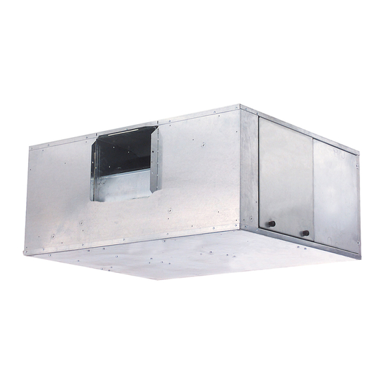
WASHER AND
DOUBLE NUT
(FIELD FURNISHED
AND INSTALLED)
Fig. 1 - Component Identification (42BHE Units Shown)
Printed in U.S.A.
SAFETY CONSIDERATIONS
Air-handling equipment is designed to provide safe and
reliable service when operated within design specifications. To
avoid injury to personnel and damage to property or equip-
ment, use good judgment and follow safe practices as outlined
below when installing and operating this equipment.
NEVER REACH INTO a unit while the fan is running.
LOCK OPEN AND TAG the fan motor power disconnect
switch before working on unit. In addition, remove the
fuses and take them with you after noting this on tag.
DISCONNECT ALL POWER before attempting any
installation or service. More than one power source may be
supplied to a unit. Power to remote mounted control
devices may not be supplied through the unit.
CHECK THE WEIGHT of assembly and components to
be sure that rigging equipment can handle them safely.
NEVER PRESSURIZE a coil with a non-liquid for leak
testing. A dangerous burst may occur.
DO NOT STEAM CLEAN coils until you are sure all per-
sonnel are clear of the area.
Failure to follow these warnings will result in severe per-
sonal injury or death.
The following contains general installation instructions for
the 42BHE,BVE fan coil units. (See Fig. 1.) Refer to the unit-
wiring diagram installed on the blower housing or specific
manufacturer literature for any other type of factory-mounted
controls.
ISOLATORS
(FIELD FURNISHED AND INSTALLED)
Form 42B-3SI
AIRSTREAM™
42BHE,BVE06-40
DANGER
INTRODUCTION
A42-4258
Pg 1
2-11
Replaces: 42B-2SI
Advertisement
Table of Contents

Related Manuals for Carrier AIRSTREAM 42BHE


Summary of Contents for Carrier AIRSTREAM 42BHE
-
Page 1: Table Of Contents
AIRSTREAM™ 42BHE,BVE06-40 System Fan Coil Air Conditioners Installation, Start-Up and Service Instructions CONTENTS SAFETY CONSIDERATIONS Page Air-handling equipment is designed to provide safe and SAFETY CONSIDERATIONS ..... . 1 reliable service when operated within design specifications. -
Page 2: Introduction
Check all critical di- contact your local Carrier representative immediately. mensions such as pipe, wire and duct connection requirements. Refer to job drawings and product dimension drawings as re- quired. -
Page 3: Step 4 - Prepare Unit
7-7/16 a42-4259 1" SUPPLY AIR COLLAR TOP VIEW DEPTH BOTH SIDES 4 X 4 JBOX AND MOTOR AND FRONT 2-1/16 MOUNTED SAME SIDE AS 1-7/16 PANEL WITH COIL CONNECTIONS CAMLOCK ACCESS 4-3/8 ADD 2" FOR MERV11 FILTER HEIGHT COIL RETURN CONN. RETURN AIR COIL SUPPLY CONN. -
Page 4: Step 6 - Make Piping Connections
“C” INCHES FROM BOTTOM ping damage or mishandling. If leaks are found, notify your lo- OF UNIT TO FINISHED FLOOR (42BVE UNIT) OR TO FALSE cal Carrier representative before initiating any repairs. CEILING (42BHE UNIT). CLEAN-OUT CAUTION NOTE: Dimension C is the total of A + B + the pipe diameter. -
Page 5: Step 7 - Make Electrical Connections
Refer to Step 7 — Make Electrical Connections — Table 3 — 42BHE,BVE ELECTRIC HEATER DATA the unit rating plate for supply voltage, motor and heater am- perage, and required circuit ampacities. (See Tables 2 - 4.) The FULL LOAD AMPS unit wiring diagram shows all factory and field wiring. -
Page 6: Step 8 - Make Duct Connections
Install all duct- Step 8 — Make Duct Connections — work to and from unit in accordance with all applicable codes. Duct construction must allow unit to operate within the limits of the unit external static pressure as shown on job submittals. Units designed to operate with ductwork may be damaged if operated without the intended ductwork attached. -
Page 7: Start-Up
7. TURN POWER ON. (Close unit electrical disconnect.) humid setting, condensation will form on many parts of the unit. In order to avoid excessive condensation, water of higher NOTE: Be sure power is off before making any adjust- temperature should be used, approximately 65 to 70 F. Also, the ments inside unit. -
Page 8: Recommended Maintenance
To remove filter, slide filter out of filter rack from either side TROUBLESHOOTING of return-air duct collar. Excessive Condensation on Fan Coil Unit THROWAWAY OR PLEATED FILTER — Replace filter Excessive condensation can be caused by running Parts — with a good quality filter of the size shown in Table 1. Do not chilled water through a fan coil unit with its fan off. - Page 10 Copyright 2011 Carrier Corporation Manufacturer reserves the right to discontinue, or change at any time, specifications or designs without notice and without incurring obligations. Catalog No. 04-53420006-01 Printed in U.S.A. Form 42B-3SI Pg 10 2-11 Replaces: 42B-2SI...
-
Page 11: Start-Up Checklist
Start-Up Checklist The following is a checklist to be completed before start-up: 1. General visual unit and system inspection Yes No 2. Check that unit is level Yes No 3. Record electrical supply voltage Yes ... -
Page 12: Manufacturer Reserves The Right To Discontinue, Or Change At Any Time, Specifications Or Designs Without Notice And Without Incurring Obligations
Technician _____________________________________ Date _____________________________________________ Customer Representative __________________________________ Date _____________________________________________ Copyright 2011 Carrier Corporation Manufacturer reserves the right to discontinue, or change at any time, specifications or designs without notice and without incurring obligations. Catalog No. 04-53420006-01 Printed in U.S.A. Form 42B-3SI...
Need help?
Do you have a question about the AIRSTREAM 42BHE and is the answer not in the manual?
Questions and answers