Table of Contents
Advertisement
Quick Links
Advertisement
Table of Contents

Related Manuals for DSPM Defender III


Summary of Contents for DSPM Defender III
- Page 1 D S P M Inc. User’s Manual Defender III & Defender III HE Uninterruptible Power System / Central Lighting Inverter User’s Manual #018-0056-04 Revision L Phone: (714) 970-2304 Fax: (909) 930-3335 Web Page: www.DSPManufacturing.com Email: sales@dspmanufacturing.com...
- Page 2 Congratulations on selecting one of the fine products from DSPM, the leader in power protection technology. Our wide product offering includes Uninterruptible Power Systems (UPS), Power Conditioners, Frequency Converters Specialty Transformers. Since our beginnings DSPM has shipped many of these fine products to discerning customers for use on sensitive equipment and critical loads.
- Page 3 DSPM employee or an employee of the recipient having a need to know, without the express written consent of DSPM, and further agrees to surrender this document to DSPM when the reason for its receipt has terminated.
-
Page 4: Important Safety Instructions
4. Equipment should be locked at all times. 5. Only DSPM trained personnel should be permitted to service or maintain equipment. 6. Only accessories recognized by DSPM shall be used with this equipment. Contact DSPM if options are desired. -
Page 5: Battery Safety
It is strongly advised not to open the UPS cabinet as the components have very high voltages and touching them may be fatal. It is recommended that a technician from DSPM or a DSPM trained technician service the unit. 24 hour phone support is available for questions. -
Page 6: Section 1- Operation
SECTION 1- OPERATION 1-1 INTRODUCTION The DEFENDER UPS (uninterruptible power system) from DSPM provides an exceptional level of load protection and monitoring capabilities. The critical load is provided with conditioned, regulated, battery backed up power at all times. Both the voltage level and frequency are controlled at all times to the load. - Page 7 1-2 BENEFITS The DEFENDER is designed to fit the needs for virtually all power conditioning and UPS applications. It has been specifically designed to power all forms of modern data processing, communications, process control equipment, lighting and emergency lighting equipment. The UPS does not require any derating as other UPS products may when powering 100% electronic loads including switch-mode power supplies.
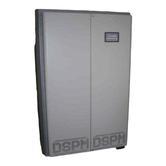
- Page 8 Typical Front View (Door(s) Closed) Phone: (714) 970-2304 Fax: (909) 930-3335 Web Page: www.DSPManufacturing.com Email: sales@dspmanufacturing.com...
- Page 9 Typical Right Hand Door View / Inverter Panel Phone: (714) 970-2304 Fax: (909) 930-3335 Web Page: www.DSPManufacturing.com Email: sales@dspmanufacturing.com...
- Page 10 Typical Left Hand Door View /Rectifier Panel Phone: (714) 970-2304 Fax: (909) 930-3335 Web Page: www.DSPManufacturing.com Email: sales@dspmanufacturing.com...
-
Page 11: Product Features
1-3 PRODUCT FEATURES The following describes the major sub-systems within the DEFENDER UPS. INPUT AND OUTPUT FILTER – The input filter reduces the input transients and harmonics on the input line. This helps protect the electronic circuitry of the UPS. The output filter filters and noise and line spikes from loads. - Page 12 MAINTENANCE BYPASS SWITCH (MBS) (optional) The MBS is a two position switch (Auto, and ByPass). The “Auto” position is the “normal” position and allows full operation of the unit with the load being fed from the inverter. The “Bypass” (MAN) position allows the load to be fed from the utility with no power provided to the inverter.
- Page 13 Hydrogen Out-gassing Switch (“HOT” Switch) (optional) The HOT switch option prevents battery charging when a system exhaust fan is not functioning. This option incorporates the usage of a “sail switch” (Honeywell # S688A 1007 , provided by others) in the exhaust ducting of the facility. Upon exhaust fan failure, the sail switch will close a contact which will eliminate the battery charging of the Defender.
- Page 14 EXTERNAL “WRAP AROUND” BYPASS SWITCH (EMBS) (optional) The EMBS is a three position switch (Auto, Test and Bypass). The “Auto” position is the “normal” position and allows full operation of the unit with the load being fed from the inverter. The “Bypass” position allows the load to be fed from the utility with no power provided to the inverter.
- Page 15 System Remote Indicator Panel (Optional) The Remote Indicator Panel provides an illuminated indication of several System operating parameters. LED indicators as labeled below. Terminations from the Remote Indicator Panel are made to the terminal block on the Inverter control panel (shown below). Terminations are as indicated. All connections must be made to the “top”...
-
Page 16: Section 2 - Preinstallation
SECTION 2 – PREINSTALLATION 2-1 SITE PLANNING AND PREPARARTION The DEFENDER is designed for installation indoors where it is protected from the elements. The UPS can be installed in a variety of different environments including computer rooms, offices, and industrial/process control locations. For the best performance and reliability, temperature extremes should be avoided. - Page 17 DE3 Emergency Lighting Inverter Utility Utility Input Output Input Output Kilo-Watts Feed Output Kilo-Watts Feed Output Voltage Voltage Voltage Voltage Amps Amps Amps Amps 22.2 66.6 28.8 22.2 66.6 28.8 33.3 88.8 14.4 38.4 33.3 88.8 14.4 38.4 44.4 111.0 19.2 48.1 44.4...
-
Page 18: Section 3 - Installation
File a claim with the shipping agency for any damage caused by shipping. Forward a copy of the damage claim to DSPM. Mount the UPS system so each side and the top has six inches of clearance for airflow. - Page 19 is hard wired in conduit. Size the branch circuit feeder conductors according to the specific power rating of the unit. Refer to the latest edition of National Electric Code (NEC) for the exact wire size required. An insulated grounding conductor must be installed as part of the input circuit. Size the grounding conductor in accordance with NEC and local codes.
-
Page 20: Input Connections
Verify that the input voltage as stated on the UPS nameplate, matches the customer-supplied voltage. If the voltage does not match, STOP installation of the UPS and contact Customer Service at DSPM. Verify that Input cable and conduit are routed correctly and are in position to connect the unit. - Page 21 If the voltage does not match, or the intended applied load exceeds unit capacity, STOP installation of the UPS and contact Customer Service at DSPM. 2. Verify that Output cable(s) and conduit(s) are routed correctly and are in position to connect the unit.
- Page 22 3-4 BATTERIES AND BATTERY CABLES WARNING!! FOLLOW THE BATTERY SAFETY PROCEDURE IN THE FRONT OF THIS MANUAL. The UPS system has fixed battery trays. All battery systems connect the batteries in series, i.e. plus terminal to minus terminal from one battery to another battery.
- Page 23 BATTERY SYSTEM TEST 1. Make sure A.C. input circuit breaker is OFF. 2. Make sure battery circuit breakers are OFF. 3. Use a meter and note the D.C. voltage at the battery circuit breaker. The voltage must be the correct polarity positive lead of the meter to the positive terminal of the circuit breaker.
-
Page 24: Section 4 - Operations
SECTION 4 - OPERATIONS 4-1 STARTING THE UPS 1. Check the input A.C. Circuit Breaker is OFF. 2. Check all output Circuit Breaker(s) (optional) are OFF. 3. Check the Battery Circuit Breaker(s) are OFF. 4. Energize the Utility feeder to the unit. 5. - Page 25 4-2 History Log Key: The History Log is used to record certain events that reflect the status and operating mode of the unit. There are 64 lines (00 through 63). It is read by holding down the Alarm Scan button. Each time the button is pressed, the log is read sequentially with the most recent event being displayed first.
- Page 26 If the voltage does not match, or the intended applied load exceeds unit capacity, STOP installation of the UPS and contact Customer Service at DSPM. 4-3 TURNING THE UPS SYSTEM OFF 1. Turn OFF the output circuit breakers.
-
Page 27: Section 5 - Output Power
SECTION 5 - OUTPUT POWER 1. Normally on circuits can be provided. These circuits are on when AC input power is on and turned off to lower the load requirements where input AC power fails. 2. Normally off circuits can be provided. These circuits provide power only when the UPS system is on battery power. -
Page 28: Section 6 - Technical Support
SECTION 6 - TECHNICAL SUPPORT 1. For Technical Support or any questions not covered in this manual, contact: DSPManufacturing 5407 E. La Palma Avenue Anaheim, CA 92807 714.970.2304 Phone 714.970.6171 Fax Service: 714.970.2304 – 8:00 AM to 5:00 PM PST 951. -
Page 29: Section 7 - Maintenance
SECTION 7 - MAINTENANCE CAUTION: DO NOT DISPOSE OF BATTERIES IN FIRE CAUTION: DO NOT ATTEMPT TO OPEN THE BATTERIES CAUTION: THE FOLLOWING PRECAUTIONS SHOULD BE TAKEN WHEN REPLACING ANY BATTERIES: • REMOVE WATCHES, RINGS, ETC… • USE TOOLS WITH INSULATED HANDLES. CAUTION: USE RUBBER PROTECTIVE GLOVES WHEN HANDLING DAMAGED BATTERIES. - Page 30 LEAD POSTS AND THEY ARE VERY EASY TO COMPRESS AND WILL CAUSE FAILURES IN THE FUTURE. Note: If Batteries are found to be leaking or fail the load test they should be replaced. (Consult DSPM as to the status of your Battery Warranty) b. Annual CAUTION: BEFORE PERFORMING ANY OF THE FOLLOWING STEPS BESURE THAT THE UPS/EMERGENCY LIGHTING INVERTER HAS BEEN TUNED OFF.
- Page 31 COMPRESS AND WILL CAUSE FAILURES IN THE FUTURE. Note: If Batteries are found to be leaking or fail the load test they should be replaced. (Consult DSPM as to the status of your Battery Warranty) Phone: (714) 970-2304 Fax: (909) 930-3335 Web Page: www.DSPManufacturing.com...
-
Page 32: Section 8 - Trouble Shooting
SECTION 8 - TROUBLE SHOOTING i. If unable to resolve any problem please contact DSPM for assistance. DSPM 1921 S. Quaker Ridge Place Ontario, CA 91761 714.970.2304 909.930.3335 customerservice@dspmanufacturing.com Phone: (714) 970-2304 Fax: (909) 930-3335 Web Page: www.DSPManufacturing.com Email: sales@dspmanufacturing.com...
Need help?
Do you have a question about the Defender III and is the answer not in the manual?
Questions and answers