Advertisement
Touch Screen Wireless Keypad
For Remote Control of the 2GIG Security System
INSTALL INSTRUCTIONS
This document describes the basic installation information for the 2GIG‐
TS1 and the steps necessary to "pair" (or learn in) the Touchscreen
Wireless Keypad to the Control Panel.
Box Contents
• 2GIG‐TS1
• AC Power Supply
• AC Power Supply Bracket
• Screws and anchors
The box contents will vary depending on whether the TS1 was
TIP:
purchased as part of a kit or not.
BEFORE YOU BEGIN
Is the 900 MHz Transceiver installed in the Panel?
For the TS1 to communicate with the Control Panel, the 900 MHz
Transceiver (2GIG‐XCVR2) must be already be installed in the Control
Panel.
Does the TS1 firmware version match the Control
Panel firmware version?
The TS1 and the Control Panel are required to have the same firmware
version to fully communicate with each other (e.g. CP v1.10 and TS1
v1.10).
To check for matching firmware versions
From both the TS1 and Control Panel Home Screen, choose Security
1
/ Menu / Toolbox.
From the Toolbox Screen, use the → arrow un l you see the Version
2
Screen.
TS1 Version Screen
Control Panel Version Screen
2GI
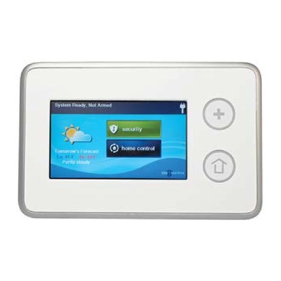
TS1 PRODUCT OVERVIEW
The Model 2GIG‐TS1 Touch Screen Wireless Keypad is a remote control
device that offers the functionality of a system keypad but also extends
all user control of the 2GIG Control panel to other locations in a user's
home. Using the TS1, users can control lights, thermostat and door locks
and see the status of every zone in their home using the exact same and
familiar interface found on the Control Panel. The keypad is designed for
indoor use only.
IMPORTANT:
Not for UL 985 installations.
The panel
and
buttons serve as controls as well as indicators.
Pressing the
(Emergency) button displays emergency icons on the
display for Panic, Fire, and Emergency alarm activation (each has
programmable options and can be enabled or disabled). Pressing the
(Home) button changes the system display to the Home Screen. The
keypad is powered from a plug‐in power supply. The 2GIG‐TS1 exchanges
information through a secure 2‐way wireless connection with the Control
Panel.
NOTE:
Before using the TS1 it must be "learned" into the Control
Panel.
Mounting Tools
Some special tools may be required to mount the TS1 onto the wall:
• Screwdriver
• Pencil
• Wire stripper
• Staple gun
• Drywall saw (or equivalent)
• Ladder
PREPARING THE KEYPAD
1 Remove the screw.
2 Flip open the back cover of the TS1.
3 Disconnect the hanging strap.
4 Use the back cover as the mounting plate.
NOTE:
Check that the TS1 Keypad is functioning before selecting a
location for the Keypad.
Advertisement
Table of Contents

Subscribe to Our Youtube Channel
Related Manuals for 2gig Technologies Touch Screen Wireless Keypad


Summary of Contents for 2gig Technologies Touch Screen Wireless Keypad
-
Page 1: Before You Begin
Touch Screen Wireless Keypad For Remote Control of the 2GIG Security System INSTALL INSTRUCTIONS TS1 PRODUCT OVERVIEW The Model 2GIG‐TS1 Touch Screen Wireless Keypad is a remote control This document describes the basic installation information for the 2GIG‐ device that offers the functionality of a system keypad but also extends TS1 and the steps necessary to “pair” (or learn in) the Touchscreen all user control of the 2GIG Control panel to other locations in a user’s Wireless Keypad to the Control Panel. home. Using the TS1, users can control lights, thermostat and door locks Box Contents and see the status of every zone in their home using the exact same and familiar interface found on the Control Panel. The keypad is designed for • 2GIG‐TS1 indoor use only. • AC Power Supply • AC Power Supply Bracket IMPORTANT: Not for UL 985 installations. • Screws and anchors The panel and buttons serve as controls as well as indicators. The box contents will vary depending on whether the TS1 was TIP: Pressing the (Emergency) button displays emergency icons on the purchased as part of a kit or not. -
Page 2: Mounting The Keypad
22 AWG 2‐pairs 110 feet (33.5 meters) (19 AWG equivalent) 18 AWG 135 feet (41.1 meters) To ensure that the appropriate wire size and length are installed, measure the voltage between the power connection terminals at the back of the control panel. The voltage measured must not fall below 11 volts DC or nuisance “AC Power Loss” messages may be displayed and reported. NOTE: In the United States, wiring routed inside walls, ceilings, and floors must comply with requirements of the National Electrical Code, ANSI/NFPA 70 and local building codes. For wiring from the output of the 2GIG class II power supply, wiring rated CL2, CL2X, CL2R, or PLTC is recommended to satisfy these requirements. If this wiring is installed in an air plenum (space used for environmental air exchange) it must be rated CL2P A Left Terminal 14 VDC(+) (plenum rated). B Right Terminal 14 VDC (-) C 18 AWG/2-Conductor ©2013 2GIG Technologies Inc. All Rights Reserved. - Page 3 Make sure that the TS1 has power from the supplied AC transformer. Connect the AC adapter to the TS1. Confirm that the wires are connected using the correct polarity. As the TS1 powers up, the following message is visible on the display. Set the RF Keypad Equipment Code to 1059 by pressing the ↓ arrow until “(1059) 2GIG‐TS1 wireless touchscreen keypad” appears. Press the ↓ arrow to advance to the next op on. From the Control Panel’s Installer Toolbox, select System Configuration. Select the Go To button. To go to question 4, enter 04. Learn the TS1 into the Control Panel. A er pressing the ↓ arrow in the previous step, the Learn button appears. Select the RF Keypad number to assign to the TS1. Use the → arrow to select the RF Keypad number (1‐4). After selecting the RF Keypad number, press the ↓ arrow to start configuring the specific parameters for the RF Keypad. INITIATING THE PAIRING PROCESS Initiate the pairing process at the Control Panel by pressing the Learn button. Press the → arrow or press the number 1 on the keypad toggle the se ng on the first ques on to “used”. Press the ↓ arrow to con nue configuring options. On the Control Panel press the Learn button. ©2013 2GIG Technologies Inc. All Rights Reserved.
- Page 4 TIP: The logo on the bottom corner of the Home Screen does not Control Panel is in system configuration (programming) mode. access the Installer Toolbox on the TS1. Repeat the steps above to learn in additional TS1s. To exit programming, click skip then end and exit. Upon exit, the Control Panel takes a several seconds to reboot. REMOVING A TS1 FROM A CONTROL PANEL (UNLEARNING THE TS1) If a user presses the logo on the bottom corner of the TS1 Home Screen, the user can enter the duress code only. Installers must remember that To remove a TS1 from a Control Panel’s configuration do the following: the Installer Toolbox can only be accessed from the Control Panel. The From the Control Panel, go to Installer Toolbox / System TS1 cannot access the Installer Toolbox. Configuration. TIP: Although there is a default master code: 1111, there is no Select the Go To button and enter 04. The Control Panel displays default duress code. Q4: select RF keypad # (1 to 4). Select the configured TS1 you wish to remove and press the ↓ arrow. Mark the RF Keypad number selected as “unused” by pressing the → arrow. This action toggles the setting on the first question between ©2013 2GIG Technologies Inc. All Rights Reserved.
-
Page 5: Regulatory Information
Visit web site for technical support hours of operation NOTICE: The Industry Canada label identifies certified equipment. This certification means that the equipment meets certain For technical support outside of the USA and Canada: telecommunications network protective, operational and safety Contact your regional distributor requirements. The Department does not guarantee the equipment will Visit dealer.2gig.com for a list of distributors in your region. operate to the user’s satisfaction. Before installing this equipment, users should ensure that it is permissible to be connected to the facilities of the local telecommunications company. The equipment must also be installed using an acceptable method of connection. The customer should be aware that compliance with the above conditions may not prevent degradation of service in some situations. Repairs to certified equipment should be made by an authorized Canadian maintenance facility designated by the supplier. Any repairs or PN 77‐000090‐001 Rev. A alterations made by the user to this equipment, or equipment malfunctions, may give the telecommunications company cause to request the user to disconnect the equipment. Users should ensure for their own protection that the electrical ground connections of the power utility, telephone lines and internal metallic water pipe system, if present, are connected together. This precaution may be particularly important in rural areas. ©2013 2GIG Technologies Inc. All Rights Reserved.
Need help?
Do you have a question about the Touch Screen Wireless Keypad and is the answer not in the manual?
Questions and answers