Advertisement
Quick Links
2GIG-TS2-E WIRELESS TOUCH SCREEN KEYPAD
INSTALLATION INSTRUCTIONS
The Wireless Touch Screen Keypad (2GIG-TS2-E) is a wall-mounted, full-color, touch screen interface
that provides many of the same easy-to-use keypad functions available on the control panel. It is
designed for indoor use only and gives users the ability to control lights, thermostats, and door locks, as
well as to view the status of every sensor zone.
When the 900 MHz Transceiver Module (2GIG-XCVR2-345 / 2GIG-XCVR2E-345) is installed in the
control panel, the system can be programmed to communicate with up to four (4) Wireless Touch
Screen Keypads.
IMPORTANT: This keypad does not support UL 985 installations.
Box Contents
Verify that the package includes the following:
●
1—Wireless Touch Screen Keypad
●
1—A C Adapter
●
1—A C Adapter Bracket (with adhesive-backing)
●
1—Plastic Zip Tie
●
3—Plastic Wall Anchors and Phillips Head Screws
TIP: The box contents will vary depending on whether the keypad was purchased as part of a kit or not.
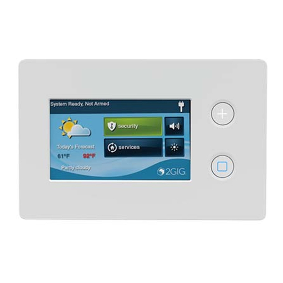
Figure 1 — Wireless Touchscreen Keypad
A Emergency Button
. Displays Panic, Fire, and Emergency alarm activation (each has
programmable options and can be enabled or disabled).
B Home Button
. Changes the screen display to the Home screen.
C Secret Duress Button. Users can press the button while the system is armed or disarmed and then
enter a Duress User Code to send a silent duress report to the central station. To learn more, see the
control panel's User Guide.
TIP: The Secret Duress button does not provide installers with the ability to access the Installer
Toolbox from the keypad. The Installer Toolbox is only available on the control panel.
Minimum Requirements
For successful communications, the system must meet these minimum requirements:
●
A 900 MHz Transceiver Module (2GIG-XCVR2e-345) must be installed in the control panel.
●
The 2GIG Panel must be running the minimum Firmware version as shown below based on the
platform of the panel or higher.
●
The TS2-E keypad must be running Version 1.16 or later. See Verifying the Firmware Version on
Both Devices.
Platform
XCVR Model
GC2e
2GIG-XCVR2e-345*
2GIG-XCVR2-345
GC2***
2GIG-XCVR2-345
* – XCVR2e model is not compatible with GC2
** – FW for GC2/GC2e must be at the minimum or higher
*** – TS2 FW may require downgrading to 1.16 for use with GC2
See section above "Verifying the FW Version on Both Devices" for further details.
Installing the Keypad
Ideally, the keypad should be mounted to a wall at about eye level. In addition:
●
The location must have AC power available and nearby.
●
Avoid locations with studs, electrical wires, and/or pipes.
Recommended Tools
The following tools are recommended when
mounting the keypad to the wall:
●
#6 Insulated Spade Terminals
●
Drywall Saw (or equivalent)
●
Ladder
●
Pencil
●
Screwdriver
●
Staple Gun
●
Wire (for details, see Determining the Wire
Gauge and Maximum Length)
●
Wire Stripper
Mounting the Keypad to the Wall
To mount the keypad to the wall:
1
Remove the screw from the back cover (see A in Fig. 2).
2
Flip open the back cover.
3
Remove the plastic hanging strap (see C in Fig. 3) from the
inside of the back cover. You will use the back cover as the
mounting plate.
4
Temporarily detach the Hanging Strap from the mounting
plate (see C in Fig. 3).
5
Leave the other end of the plastic strap attached to the
circuit board (see D in Fig. 3).
A
C
B
FW Version**
(Minimum Required)
1.23
1.23
1.16
Figure 2 — Back Cover
B
A
Figure 3 — Remove Hanging Strap
C
Figure 4 — Mounting Holes
6
Hold the back cover at the desired location
on the wall. Then use pencil to mark the
location of the power wire (see A below)
and screw holes (see B in Fig. 4).
Use a drywall saw to cut an access hole
7
for the power wire (see A in Fig. 4).
Figure 5 — Mounting Plate
8
Attach the mounting plate to the
wall using the three screw holes
B
(see B in Fig. 5).
Determining the Wire Gauge and Maximum Length
To determine the appropriate wire gauge and length to use, measure the voltage output of the control
panel's power terminals. The terminals are located on the back of the control panel.
TIP: To avoid the reporting and display of nuisance "AC Power Loss" messages, the measured voltage
must not fall below 14 Volts DC.
Use the table below as a guide for selecting the gauge for the power wires. To ensure proper operation,
do not exceed the following maximum length for the wire gauge installed:
Wire Gauge
22 AWG
20 AWG
22 AWG 2-pairs (19 AWG equivalent)
18 AWG
IMPORTANT: In the United States, wiring routed inside walls, ceilings, and floors must be in compliance
with the requirements for NFPA 70: National Electric Code and local building codes. To satisfy these
requirements, it is recommended that the wiring from the AC Power Adapter output be rated CL2, CL2X,
CL2R, or PLTC. When installing wiring in a plenum space (e.g., a pathway used to facilitate air circulation
for heating and air conditioning systems) the wire must be plenum-rated (CL2P).
Connecting the Power to the Keypad
There are two ways to provide power to the keypad. If you are using wires, see section above for
appropriate wires to be applied. If you will be connecting power using the barrel connection option, skip
down below to Barrel Power Connection Option section. Only one power connection type is required.
NOTE: These keypads include a built-in, 90-degree, four (4)-pin header for use with the Firmware
Update Cable (2GIG-PCBL2).
To connect the power to the Keypad using power wires:
1
Reconnect the plastic hanging strap to the inside of the back
cover (see A in Fig. 6a).
2
Route the power supply wire to the power terminals on the
Keypad 1 (see B in Fig. 6a).
3
Use #6 Insulated Spade Terminals (not provided) to connect
the power wires to the keypad. The connections are polarity
sensitive. Always observe the (+) and (-) markings on the unit
(see B in Fig. 6a).
4
Move ahead to step 8 & 9 to reattach the back cover to the
keypad.
To connect power using the Barrel Power Connection Option:
NOTE: (2GIG-AC2-PLUG / 2GIG-AC2-INT sold separately).
Route barrel connector cable through the back panel opening
5
(see C in Fig. 6b below).
6
Locate the barrel connector port (see D in Fig. 6b below), and
insert the connector to the port.
7
Follow steps 8 and 9 below to reattach the back cover to the
keypad.
C
D
Figure 7 — Close Back Cover
8
Align and snap the back cover closed (see A in Fig. 7).
9
Reattach the screw to the back cover(see B in Fig. 7).
10 Connect the other side of the power wiring to the AC
Adapter (provided). The connections are polarity sensitive.
Always observe the (+) and (-) markings as follows:
●
Left Terminal 14 VDC (+). See A in Fig. 8.
●
Right Terminal 14 VDC (-). See B in Fig. 8.
NOTE: The power wire (see C in Fig. 8) goes to the keypad.
A
B
B
B
A
B
B
Maximum Length
55 feet (16.8 meters)
85 feet (25.9 meters)
110 feet (33.5 meters)
135 feet (41.1 meters)
A
Figure 6a — AC Adapter
Figure 6b — Power with Barrel Connector
Figure 8 — AC Adapter
B
A
B
A
B
C
Advertisement

Related Manuals for 2gig Technologies 2GIG-TS2-E


Summary of Contents for 2gig Technologies 2GIG-TS2-E
- Page 1 Figure 4 — Mounting Holes Hold the back cover at the desired location The Wireless Touch Screen Keypad (2GIG-TS2-E) is a wall-mounted, full-color, touch screen interface on the wall. Then use pencil to mark the that provides many of the same easy-to-use keypad functions available on the control panel. It is...
- Page 2 This device complies with Industry Canada licence-exempt RSS standard(s). Operation is subject to the ● On the control panel at the Pair with Xcvr Device screen, ensure the Type reads 2GIG-TS2-E following two conditions: (1) this device may not cause interference, and (2) this device must accept any Wireless Touch Screen Keypad and that the ID# appears.
Need help?
Do you have a question about the 2GIG-TS2-E and is the answer not in the manual?
Questions and answers