
Related Manuals for Viper 106V


Summary of Contents for Viper 106V
- Page 1 1 1 0 0 6 6 V V I I n n s s t t a a l l l l a a t t i i o o n n G G u u i i d d e e ©...
-
Page 2: Table Of Contents
. . .6 I I M M P P O O R R T T A A N N T T ! ! The Viper 106V system is designed to be installed in any petrol or common rail diesel vehicle with a 12-volt battery. -
Page 3: What Is Included
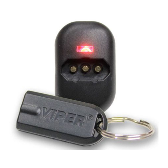
One hardware pack system configuration The Viper 106V system has a control module which works in conjunction with a touch- key to allow the vehicle to be started. A total of 3 touch-keys can be programmed into the control module. -
Page 4: Wire Connection Guide
wire connection guide immobiliser harness wiring diagram N N O O T T E E : : All wires are BLACK. Each pair is an immobiliser circuit input and output. Each wire is marked with its function. The descrip- tion listed below is the marking on each wire and then its function, in brackets. -
Page 5: Touch-Key Harness Wiring Diagram
touch-key harness wiring diagram N N O O T T E E : : All wires are BLACK. Each wire is marked with its func- tion. The Touch-Key harness has 3-pin connectors to facilitate the connection from the control module to the Touch-Key recep- tacle. -
Page 6: Immobiliser Harness Wiring
immobiliser harness wiring guide This guide describes in detail the connection of each wire. Please read the instructions carefully to ensure a thorough understanding of this unit and how it operates. Locate the main ignition, starter and fuel pump circuit wires with a multimeter. Cut the appro- priate wire and attach the key side and car side wires to the corresponding wires on the 6-wire immobiliser harness. -
Page 7: Touch-Key Receptacle Wiring
N N O O T T E E : : The Viper 106V control unit must be installed inside the vehicle. Under no circumstances should the unit be installed under the bonnet or other similarly hostile environment. -
Page 8: Programming Instructions
programming instructions Use the procedure below to program touch-keys into the system. A maximum of 3 touch-keys can be programmed into the system. N N O O T T E E : : In order to program touch-keys into the system, the sys- tem must be disarmed. -
Page 9: Wiring Reference Guide
FUEL PUMP OUTPUT FUEL PUMP GROUND BOTH OF THE WIRES FROM THE 106V IF NOT USED. N N O O T T E E : : The current draw for the entire system is less than 9 mA. Power supply voltage range is 9 to 16 volts. The current handling capacity for each immobilisation circuit is 20amps continuous/30amps peak. -
Page 10: Notes
notes ________________________________________ ________________________________________ ________________________________________ ________________________________________ ________________________________________ ________________________________________ ________________________________________ ________________________________________ ________________________________________ ________________________________________ ________________________________________ ________________________________________ ________________________________________ ________________________________________ ________________________________________ ________________________________________ ________________________________________ ________________________________________ ________________________________________ ________________________________________ ________________________________________ ________________________________________ ________________________________________ ________________________________________ ________________________________________ ________________________________________ ________________________________________ www.directed.com...
Need help?
Do you have a question about the 106V and is the answer not in the manual?
Questions and answers