Table of Contents
Advertisement
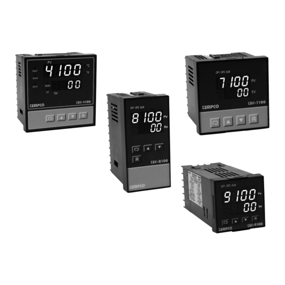
TEC-4100 / 7100 / 8100 / 9100
Auto-Tune Fuzzy / PID Process
Temperature Controller
Serving Industry Since 1972
Instruction Manual
Agency Approvals
TEMPCO Electric Heater Corporation
607 N. Central Avenue • Wood Dale, IL 60191-1452 USA
Tel: 630-350-2252 • Toll Free: 800-323-6859
Fax: 630-350-0232 • E-mail: info@tempco.com
Web: www.tempco.com
Manual TEC-100 Revision 9/2013
Advertisement
Table of Contents

Related Manuals for Tempco TEC-4100


Summary of Contents for Tempco TEC-4100
- Page 1 Instruction Manual TEC-4100 / 7100 / 8100 / 9100 Auto-Tune Fuzzy / PID Process Temperature Controller Agency Approvals TEMPCO Electric Heater Corporation 607 N. Central Avenue • Wood Dale, IL 60191-1452 USA Tel: 630-350-2252 • Toll Free: 800-323-6859 Fax: 630-350-0232 • E-mail: info@tempco.com Serving Industry Since 1972 Web: www.tempco.com...
- Page 2 NOTES...
-
Page 3: Table Of Contents
Figure 2.4 Rear Terminal Connection for TEC-4100 and TEC-8100 ....8 2-1 Unpacking ........7 Figure 2.5 Rear Terminal Connection for TEC-7100 . - Page 4 NOTES...
-
Page 5: Chapter 1 Overview
Fuzzy technology. is a 72×72 DIN size panel mount controller. TEC-8100 is a 1/8 DIN size panel mount controller and TEC-4100 is a 1/4 DIN size panel mount controller. These units are powered by 11–26 or 90–250 VDC/VAC 50/60 Hz supply, incorporating a 2 amp con- trol relay output as standard. -
Page 6: Ordering Code
Data Communication Accessories: TEC99001 Smart Network Adapter for third party SCADA software TEC99030 "Tempco Config Set" PC software for use with TEC99003 which converts 255 channels of RS-485 or RS-422 to RS- Smart Network Adapter. (can be downloaded at no charge 232 Network. -
Page 7: Programming Port
The left diagram shows program number 6 Press for 7.4 seconds to select auto-tuning mode. for TEC-9100 with version 12. The program no. for TEC-7100 is 13, for Press for 8.6 seconds to select calibration mode. TEC-8100 is 11 and for TEC-4100 is 12. -
Page 8: Menu Overview
1–5 Menu Overview... -
Page 9: Parameter Descriptions
1–6 Parameter Descriptions Continued…... - Page 10 Parameter Descriptions, Continued…...
-
Page 11: Chapter 2 Installation
Write down the model number, serial number, and date code for future reference when corresponding with Tempco. The serial number (S/N) and date code (D/C) are labeled on the box and the housing of the control. NOTE: The TEC-9100 Series may be supplied with either mounting screws (2) or mounting clamps (2). -
Page 12: Wiring Precautions
2–3 Wiring Precautions Before wiring, verify the correct model number and options on the label. Switch off the power while checking. Care must be taken to ensure that the maximum voltage rating specified on the label is not exceeded. It is recommended that the power for these units be protected by fuses or cir- cuit breakers rated at the minimum value possible. -
Page 13: Power Wiring
2–4 Power Wiring The controller is designed to operate at 11–26 VAC/VDC or This equipment is designed for installation in an enclo- 90–250 VAC. Check that the installation voltage corresponds to sure which provides adequate protection against electric the power rating indicated on the product label before connect- shock. - Page 14 Control Output Wiring, continued…...
-
Page 15: Alarm Wiring
2–8 Alarm Wiring 2–9 Data Communication If you use a conventional 9-pin RS-232 cable instead of TEC 99014, the cable must be modified according to the following circuit diagram. -
Page 16: Chapter 3 Programming
Chapter 3 Programming 3–2 Signal Input Press for 5 seconds and release to enter the setup menu. Press to select the desired parameter. The upper display indi- INPT: Selects the sensor type or signal type for signal input. cates the parameter symbol, and the lower display indicates the Range: (thermocouple) J-TC, K-TC, T-TC, E-TC, B-TC, selected value of the parameter. - Page 17 Control Outputs, continued… Heat only ON-OFF control: Select REVR for OUT1. Set PB Cool only control: ON-OFF control, P (PD) control, and PID (proportional band) to 0. O1HY is used to adjust dead band for control can be used for cool control. Set OUT1 to DIRT (direct ON-OFF control.
-
Page 18: Alarm
3–4 Alarm 3.3 & 3.4 Alarm Figures The controller has one alarm output. There are six types of alarm functions and one dwell timer that can be selected, and four kinds of alarm modes (ALMD) are available for each alarm function (ALFN). Output 2 can be configured as another alarm in addition to the alarm output. -
Page 19: Configuring User Menu
3–5 Configuring User Menu 3–7 Dwell Timer Most conventional controllers are designed with a fixed order in The alarm output can be configured as a dwell timer by selecting which the parameters scroll. The x100 series have the flexibility TIMR for ALFN (alarm function). As the dwell timer is config- to allow you to select those parameters which are most significant ured, the parameter SP3 is used for dwell time adjustment. -
Page 20: Pv Shift
3–8 PV Shift In certain applications it is desirable to shift the controller display value (PV) from its actual value. This can easily be accomplished by using the PV shift function. The SHIF function will alter PV only. Example: A process is equipped with a heater, a sensor, and a subject to be warmed up. -
Page 21: Auto-Tuning
3–11 Auto-tuning The auto-tuning process is performed near the set point. The process will oscillate around the set point during the tuning process. Set the set point at a lower value if overshooting beyond the normal process value is likely to cause damage. -
Page 22: Manual Control
3–13 Manual Control 3–15 Process Variable (PV) Retransmission The controller can output (retransmit) the process value via Operation To enable manual control, the LOCK parameter should be set its retransmission terminals RE+ and RE- provided that the to NONE, then press for 6.2 seconds;... -
Page 23: Chapter 4 Applications
Chapter 4 Applications 4–1 Heat Only Control with Dwell Timer An oven is designed to dry products at 150°C for 30 minutes and then stay unpowered for another batch. A TEC- 8100 equipped with dwell timer is used for this purpose. The system dia- gram is shown as follows: To achieve this function, set the fol- lowing parameters in the setup menu:... -
Page 24: Heat-Cool Control
4–3 Heat-Cool Control An injection mold is required to be controlled at 120°C to ensure a consistent quality for the parts. An oil pipe is buried in the mold. Since plastics are injected at a higher temperature (e.g., 250°C), the circulation oil needs to be cooled as its temperature rises. Here is an example: The PID heat-cool is used for the example at left. -
Page 25: Chapter 5 Calibration
Chapter 5 Calibration Manual Calibration Procedures Do not proceed through this section unless there is a def- inite need to recalibrate the controller. If you recalibrate, • Perform step 1 to enter calibration mode. all previous calibration data will be lost. Do not attempt recali- bration unless you have the appropriate calibration equipment. - Page 26 Manual Calibration Procedures… Step 6. Set up the equipment according to the diagram above for calibrating the cold junc- tion compensation. Note that a K type thermocouple must be used. The 5520A calibrator is configured as K type thermocouple output with inter- nal compensation.
-
Page 27: Chapter 6 Specifications
Chapter 6 Specifications Power 90–250 VAC, 47–63 Hz, 12VA, 5W maximum 11–26VAC/VDC, 12VA, 5W maximum Input 18 bits Resolution: 5 samples / second Sampling rate: –2VDC minimum, 12VDC maximum (1 minute for mA input) Maximum rating: ±1.5uV/°C for all inputs except mA input Temperature effect: ±3.0uV/°C for mA input T/C: 0.2uV/ohm... -
Page 28: Digital Filter
Load Resistance: Dimensions: 10 K Ohms minimum (for voltage output) TEC-4100 — 3-3/4 × 3-3/4 × 2-9/16" H × W × D (96 × 96 × 65 mm) Output Regulation: 0.01% for full load charge Depth behind panel: 2" (53 mm) Output Settling Time: 0.1sec (stable to 99.9%) -
Page 29: Chapter 7 Modbus Comm
Chapter 7 Modbus Communications This chapter specifies the Modbus Communications protocol as RS-232 or RS-485 interface module is installed. Only RTU mode is supported. Data is transmitted as eight-bit binary bytes with 1 start bit, 1 stop bit and optional parity checking (None, Even or Odd). -
Page 30: Exception Responses
7-2 Exception Responses If the controller receives a message which contains a corrupted character (parity check error, framing error etc.), or if the CRC16 check fails, the controller ignores the message. However, if the controller receives a syntactically correct message which contains an illegal value, it will send an exception response, consisting of five bytes as follows: slave address +offset function code + exception code + CRC16 Hi +CRC16 Lo Where the offset function code is obtained by adding the function code with 128 (ie. - Page 31 Register Parameter Parameter Scale Scale Notes Address Notation ALFN Alarm Function 65535 High REHI Retransmission high scale value ALMD Alarm operation mode 65535 ALHY Alarm hysteresis ALFT Alarm failure transfer 65535 COMM Communication function 65535 ADDR Address 65535 BAUD Baud rate 65535 DATA Data bit count...
-
Page 32: Data Conversion
-1999.9 -199.99 -19.999 Scale High 4553.6 4553.6 45536 4553.6 455.36 45.536 For TEC-9100, TEC-8100, TEC-7100 and TEC-4100: Conditions Non-linear Linear input Linear input Linear input Linear input input DP = 0 DP = 1 DP = 2 DP = 3 Scale low -1999.9... -
Page 33: Communication Example
7-5 Communication Examples: Example 1: Download the default values via the programming port The programming port can perform Modbus communications regardless of the incorrect setup values of address, baud, parity, stop bit, etc. It is especially useful during the first time configuration for the controller. The host must be set with 9600 baud rate, 8 data bits, even parity and 1 stop bit. -
Page 34: Error Codes
Table A.1 Error Codes and Corrective Actions... -
Page 35: Warranty
Tempco Electric Heater Corporation is pleased to offer sugges- No product returns can be accepted without a completed Return tions on the use of its products. However, Tempco makes no war- Material Authorization (RMA) form. ranties or representations of any sort regarding the fitness for TECHNICAL SUPPORT use, or the application of its products by the Purchaser. - Page 36 The Electric Heating Element, Temperature Controls and Temperature Sensors Handbook REQUEST YOUR FREE 960 PAGE COPY TODAY! Call (800-323-6859) or E-mail (info@tempco.com) Specify Print Edition, CD-ROM or Both Serving Industry Since 1972 Experience the Advantages of our Diverse and Innovative Products TEMPCO Electric Heater Corporation 607 N.
Need help?
Do you have a question about the TEC-4100 and is the answer not in the manual?
Questions and answers