Table of Contents
Advertisement
Instruction Manual
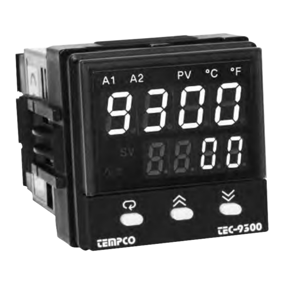
TEC-9300
Self-Tune Fuzzy / PID Process
Temperature Controller
Agency Approvals: RoHS
TEMPCO Electric Heater Corporation
607 N. Central Avenue • Wood Dale, IL 60191-1452 USA
Tel: 630-350-2252 • Toll Free: 800-323-6859
Fax: 630-350-0232 • E-mail: info@tempco.com
Web: www.tempco.com
Manual TEC-9300 Revision 9/2016
Advertisement
Table of Contents

Subscribe to Our Youtube Channel
Related Manuals for Tempco TEC-9300


Summary of Contents for Tempco TEC-9300
- Page 1 Self-Tune Fuzzy / PID Process Temperature Controller Agency Approvals: RoHS TEMPCO Electric Heater Corporation 607 N. Central Avenue • Wood Dale, IL 60191-1452 USA Tel: 630-350-2252 • Toll Free: 800-323-6859 Fax: 630-350-0232 • E-mail: info@tempco.com Web: www.tempco.com Manual TEC-9300 Revision 9/2016...
- Page 2 NOTES...
-
Page 3: Table Of Contents
Using the Manual Copyright © 2016, Tempco Electric Heater Corporation, all Installers ......Read Chapters 1, 2 rights reserved. - Page 4 NOTES...
-
Page 5: Features
PID controller would. The input signals are digitized by using an 18-bit A to D convert- er. Its fast sampling rate allows the TEC-9300 to control fast processes such as pressure and flow. Self-tuning can be used to optimize the control parameters as soon as undesired control results are observed. -
Page 6: Hardware Code
255 channels of RS-485 or RS-422 to RS-232 network TEC99003 Smart network adapter for connecting the TEC-9300 programming cable to the PCs RS-232 serial port or to a Serial → USB adapter TEC99013 Programming cable for the TEC-9300 TEC99923... -
Page 7: Programming Port And Dip Switch
1–3 Programming Port and DIP Switch Access Hole Rear Terminal Front Panel Figure 1. Access Hole ......... . Overview The programming port is used to connect to the TEC99001 for instant programming... -
Page 8: Keys And Displays
1–4 Keys and Displays The unit is programmed by using the three keys on the front panel. The available key functions are listed in the following table. Alarm 1 Indicator How to display a 5-digit number Alarm 2 / Output 2 Indicator For a number with decimal point the display will be shifted one digit right: Process Value Indicator... - Page 9 1–4 Keys and Displays continued…...
-
Page 10: Menu Overview
1–5 Menu Overview... -
Page 11: System Modes
1–6 System Modes The controller performs closed loop control in its normal control mode condition. The controller will maintain its normal control mode when you are operating the user menu, setup menu, display mode, reloading default values, or applying event input signals. Under certain conditions, the normal control mode will transfer to an exception mode. -
Page 12: Parameter Description
1–7 Parameter Description NOTE: For RS-232: Short J1, Open/Cut J2 Using RS-232 will disable Event Input Function... - Page 13 NOTE: Parameter 1N1 continued on next page...
- Page 14 NOTE: Parameter O1TY continued on next page...
- Page 17 Note: Calibration menu is for supplier configuration use only.
-
Page 19: Unpacking
Chapter 2 Installation Dangerous voltage capable of causing death can be pres- 2–3 Wiring Precautions ent in this instrument. Before installation or beginning • Before wiring, verify the correct model number and options on any troubleshooting procedures, the power to all equipment must the label. -
Page 20: Power Wiring
2–4 Power Wiring 2–5 Sensor Installation Guidelines The controller is supplied to operate at 11–26VAC/VDC or Proper sensor installation can eliminate many problems in a 90–264VAC. Check that the installation voltage corresponds to control system. The probe should be placed so that it can detect the power rating indicated on the product label before connecting any temperature change with minimal thermal lag. -
Page 21: Rtd Input Wiring
2–7 RTD Input Wiring The RTD connections are shown in figure 2.6, with the compensating lead connected to terminal 12. For two-wire RTD inputs, terminals 12 and 13 should be linked. A three-wire RTD offers the capability of lead resistance compen- sation, provided that the three leads are the same gauge and equal in length. -
Page 22: Ct/Heater Current Input Wiring
2–9 CT/Heater Current Input Wiring Make sure that the total current through TEC99999 does not exceed 100A rms in a 3-Phase system. -
Page 23: Event Input Wiring
2–10 Event Input wiring The event input can accept a switch signal as well as an open collector signal. The event input func- tion (EIFN) is activated when the switch is closed or an open collector (or a logic signal) is pulled down. -
Page 24: Output 1 Wiring
2–11 Output 1 Wiring... -
Page 25: Output 2 Wiring
2–12 Output 2 Wiring... -
Page 26: Alarm 1 Wiring
2–13, 2–14 Alarm 1 and 2 Wiring Note: Both Form A and B contacts are available for the alarm 1 relay. Order the correct form for alarm 1 to suit your needs. - Page 27 2–15 RS-485...
-
Page 28: Analog Retransmission
2–16 RS-232 Note: If the TEC-9300 is configured for RS-232 communica- tion, the EI (event input) is disconnected internally. The unit can Figure 2.19 RS-232 Wiring no longer perform event input function (EIFN). When you connect an RS-232 module (CM94-2) to the con-... -
Page 29: Input 1
Chapter 3 Programming Basic Functions This unit provides a useful parameter “FUNC” which can be used Heater break alarm to select the function complexity level before setup. If Basic Loop break alarm Mode (FUNC=BASC) is selected for a simple application, then 1. -
Page 30: Out1 And Out2 Types
Most conventional controllers are designed with a fixed order in When using the up and down keys to select the parameters, you which the parameters scroll. The TEC-9300 has the flexibility to may not see all of the above parameters. The number of visible allow you to select those parameters which are most significant parameters is dependent on the setup condition. -
Page 31: Cool Only Control
3–4 Heat Only Control continued… The ON-OFF control may introduce excessive process oscilla- not practical because the load may tion even if hysteresis is minimized to the smallest. If ON-OFF change from time to time and often OUT1 = Setup PID: control is set (i.e., PB1=0), TI1, TD1, CYC1, OFST, CPB and need to adjust OFST repeatedly. -
Page 32: Heat-Cool Control
3–6 Heat-Cool Control The heat-cool control can use one of six combinations of control modes. Setup of parameters for each control mode are shown in the following table. NOTE: The ON-OFF control may result in excessive overshoot program to optimize the PID values by selecting YES for SELF and undershoot problems in the process. -
Page 33: Dwell Timer
3–7 Dwell Timer Alarm 1 or alarm 2 can be configured as dwell timer by selecting TIMR for A1FN or A2FN, but not both, otherwise will appear. As the dwell timer is configured, the parameter TIME is used for dwell time adjustment. The dwell Er07 time is measured in minute ranging from 0 to 6553.5 minutes. -
Page 34: Process Alarms
3–8 Process Alarms When a normal alarm is selected, the There are at most two independent alarms available by Normal Alarm: A1MD=NORM alarm output is de-energized in the adjusting OUT2. If AL2 is selected for OUT2, then PV1.H, PV1.L, PV2.H, PV2.L, 8 Types of Process Alarms: non-alarm condition and energized in OUT2 will perform alarm 2 function. -
Page 35: Deviation Alarms
3–9 Deviation Alarm OUT2 can be configured as alarm 2 by selecting AL2. If AL2 is selected for OUT2, then output 2 will perform alarm 2 function. Now NONE can’t be select- ed for A2FN, otherwise Er06 will appear. A deviation alarm alerts the user when the process deviates too far from the set point. -
Page 36: Deviation Band Alarms
3–10 Deviation Band Alarm 2 types of A deviation band alarm presets two reference levels relative to set point. Two types of DB.HI, DB.LO Deviation Band Alarms: deviation band alarm can be configured for alarm 1 and alarm 2. These are deviation band high alarm (A1FN or A2FN select DB.HI) and deviation band low alarm (A1FN or A2FN select DB.LO). -
Page 37: Heater Break Alarm
3–11 Heater Break Alarm 3–12 Loop Break Alarm A current transformer (Part No. TEC99999) should be installed A1FN selects LB if to detect the heater current if a heater break alarm is required. alarm 1 is required to act Setup: A1FN = LB Loop break alarm 1 The CT signal is sent to input 2, and the PV2 will indicate the as a loop break alarm. -
Page 38: Sensor Break Alarm
3–13 Sensor Break Alarm Alarm 1 or alarm 2 can be configured as a sensor break alarm by selecting SENB for A1FN or A2FN. If alarm 2 is required as a sensor break alarm, then Setup: A1FN=SENB Sensor Break Alarm 1 AL2 should be selected for OUT2. -
Page 39: Failure Transfer
3–16 Failure Transfer The controller will enter failure mode if one of the following conditions occurs: 1. SB1E Failure mode occurs as: occurs (due to input 1 sensor break or input 1 current below 1mA if 4– 2. SB2E 20mA is selected or input 1 voltage below 0.25V if 1–5V is selected) if PV1, P1- SB1E 3. -
Page 40: Bumpless Transfer
3–17 Bumpless Transfer 3–18 Self tuning The bumpless transfer function is Self-tuning, which was designed available for output 1 and output 2 using an innovative algorithm, pro- Bumpless transfer (provided that OUT2 is configured vides an alternate option for tuning Self-tune Menu 1. -
Page 41: Auto-Tuning
will be strongly related to the time when the auto-tuning is applied. Hence, different values will be obtained every time auto- 3–19 Auto tuning The auto-tuning process is performed at the set point. tuning is completed without pre-tune. It is particularly true when auto-tuning is applied using cold start and warm start. -
Page 42: Manual Tuning
3–20 Manual Tuning In certain applications (very few), when using both self-tuning and auto-tuning to tune a process proves inadequate for the control requirements, you can try manual tuning. Connect the controller to the process and perform the procedures according to the flow chart shown in the following diagram. If the control performance using auto or self- tuning is still unsatisfactory, the following rules can be applied for further adjustment... -
Page 43: Signal Conditioner Dc Power Supply
3–21 Signal Conditioner 3–22 Manual Control DC Power Supply Manual control may be used for the following purposes: Three types of isolated DC power supplies are available to supply 1. To test the process characteristics to obtain a step response as an external transmitter or sensor. -
Page 44: Display Mode
3–23 Display Mode 3–24 Heater Current Monitoring TEC99999, a current transformer, should be equipped to meas- ure the heater current. Select CT Press several times until (display) Operation for IN2. The input 2 signal con- appears on the display. Then press to enter display mode. -
Page 45: Event Input
If chosen, the second PID set event input and RS-232. If you want to change function of the PB2, TI2, and TD2 will be used to TEC-9300 from RS-232 to event input, you must modify jumper PID2: replace PB1, TI1, and TD1 for control. -
Page 46: Second Pid Set
4–3 Second PID Set Choose SP.P2 for EIFN then both set point and PID values will In certain applications the character- Application 1: programmed by the set point be switched to another set simultaneously. istics of a process are strongly relat- Apply The signal applied to the event input may ed to its process value. -
Page 47: Remote Set Point
SPMD and PVMD, an error code will appear. In either FUNC=FULL Case 1: case, the TEC-9300 will not control properly. IN2, IN2U, DP2, IN2L, IN2H, are set according to remote sig- If PV1/PV2 is selected for SPMD, a signal loss will nal. -
Page 48: Output Power Limits
(DATA), parity bit (PARI) and stop bit (STOP) so that these val- ues are accordant with the PC RS-485 Terminals setup conditions. If the TEC-9300 is con- figured for RS-232 communica- NOTE: tion, the EI (event input) is dis- NOTE: connected internally. -
Page 49: Analog Retransmission
FILT Menu where N=3, 4 or 5. See ordering code in programmable low-pass filter section 1-2. incorporated in the TEC-9300 can FILT Filter is used to stabilize be used to improve this. This is a the process display. first order filter with the time con- Select FULL for FUNC in the setup menu. -
Page 50: Pump Control
A typical value for FILT is 0.5 or 1. mentioned above. Only the superior noise rejection capability in addition to the fast sampling rate possessed by the TEC-9300 can 4. Close the valves and observe whether the controller can shut handle such an application. -
Page 51: Pump/Pressure Control
By taking advantage of its PUMP function, the this example: TEC-9300 can be used to create an economical yet versatile solu- To supply a variable frequency AC voltage to the tion for these applications. Here is an example: motor. -
Page 52: Heat Only Control
The system marized in the following table: diagram is shown as follows: Output 1 and output 2 of the TEC-9300 can be connected to the VPFW SSR directly provided that a pulsed voltage drive output is ordered. -
Page 53: Cool Only Control
5–4 Cool Only Control A TEC-9300 is used to control a refrigerator with the temperature below 0°C. To avoid set point adjustment beyond the desired range, SP1L is set at -10°C and SP1H is set at 0°C. Because the temper- ature is lower than the ambient, a cooling action is required, so select DIRT for OUT1. -
Page 54: Ramp And Dwell
The transition interval between the high and low temperatures is required to be 5 minutes. Make the following setup: The TEC-9300 provides a 4–20mA signal to control the speed EIFN = SP.P2 of the inverter. SP.P2 is chosen for EIFN in order to create a dual A1FN = TIMR PID control. -
Page 55: Remote Set Point
If you order a TEC-9300 with a retransmission unit for the master controller, and retransmit its set point to input 2 on the rest of the slave controllers, each zone will be synchronized with the same temperature. -
Page 56: Dual Set Point/Pid
5–9 Dual Set Point/PID The TEC-9300 will switch between the two PID sets based on the process value, the set point, or either of the event inputs. As the A heat treating furnace is required to harden the mold at a high... - Page 57 PROT refer to section 2-15 and section 4-8. solution for the above application would ADDR be to use 80 TEC-9300 units plus a Smart Taking advantage of DAQ software, the BAUD Network Adapter (Part Number TEC99003) operator can monitor the process on the...
-
Page 58: Retransmit
The temperature and humidity ical reaction and temperature. He uses a TEC-9300 to control the must be recorded on a chart recorder. The preferred ranges for temperature of the solution being tested. -
Page 59: Chapter 6 Calibration
Chapter 6 Calibration Do not proceed through this section unless there is a defi- nite need to recalibrate the controller. If you do recalibrate, Press the scroll key until the display shows . Send a Step 3 all previous calibration data will be lost. Do not attempt recalibra- 60mV signal to terminals 12 and 13 with the correct polarity. - Page 60 Set the DIP switch to your desired position (refer to section 1-3). Step 12 Automatic calibration procedures The programming port (see section 2-18) of the TEC-9300 can be used for automatic calibration. The equipment required for automatic calibration is available upon request.
-
Page 61: Chapter 7 - Error Codes And
Chapter 7 Error Codes and Troubleshooting This procedure requires access to the circuitry of a unit 3. If the points listed on the above chart have been checked and under live power. Accidental contact with line voltage is the controller still does not function properly, it is recom- possible. - Page 64 NOTES...
-
Page 65: Chapter 8 Specifications
Chapter 8 Specifications 90–264VAC, 47–63Hz, 15VA, 7W maximum 18 bits Power Input 2 11–26 VAC/VDC, 15VA, 7W maximum 1.66 times/second Resolution: 18 bits -2VDC minimum, 12VDC maximum Sampling rate: 5x/second ±3.0uV/°C for mA input ±1.5uV/°C Input 1 resolution: Maximum rating: for all other inputs -2VDC minimum, 12VDC maximum Sampling rate:... - Page 66 1A/240VAC Upper 0.4" (10mm), lower Triac (SSR) Output User Interface 0.3" (8mm) 20A for 1 cycle Rating: Dual 4-digit LED displays: 3 keys 50mA rms Inrush Current: For automatic setup, calibration, and Keypad: 3mA rms Min. Load Current: testing Programming port: 1.5V rms Max.
-
Page 67: Chapter 9 Modbus Communications
Chapter 9 Modbus Communications This chapter specifies the Modbus Communications protocol as RS-232 or RS-485 interface module is installed. Only RTU mode is supported. Data is transmitted as eight-bit binary bytes with 1 start bit, 1 stop bit and optional parity checking (None, Even or Odd). Baud rate may be set to 2400, 4800, 9600, 14400, 19200, 28800 and 38400. -
Page 68: Exception Responses
9-2 Exception Responses If the controller receives a message which contains a corrupted character (parity check error, framing error, etc.), or if the CRC16 check fails, the controller ignores the message. However, if the controller receives a syntactically cor- rect message which contains an illegal value, it will send an exception response, consisting of five bytes as follows: slave address +offset function code + exception code + CRC16 Hi +CRC16 Lo Where the offset function code is obtained by adding the function code with 128 (ie. - Page 69 9-3 Parameter Table...
- Page 80 9-3 Communication Examples P= 100.0 RC 16...
-
Page 81: Menu Existence Conditions
A–1 Menu Existence Conditions... -
Page 84: Factory Menu Description
A–2 Factory Menu Description... -
Page 85: Glossary
A–3 Glossary Blackbody: A theoretical object that radiates the maximum amount of energy at a given temperature, and absorbs all the energy incident upon it. A blackbody is not necessarily black. (The name blackbody was cho- Absolute zero: The lowest theoretical temperature. At absolute zero, a sen because the color black is defined as the total absorption of light body would have no molecular motion of heat energy. - Page 86 FM-approved: An instrument that meets a specific set of specifications Current proportioning: A 4–20 milliamp (typical) current output which provides a current proportional to the amount of control established by Factory Mutual Research Corp. required. Form A: Single Pole Single Throw relay that only utilizes the N.O. and Current transformer: A transformer, intended for measuring purposes, common contacts.
- Page 87 Sensitivity: The minimum change in input signal to which an instru- Intrinsically safe: An instrument which will not produce any spark or thermal effects under normal or abnormal conditions that will ignite a ment can respond. specified gas mixture. Set point: Control setting to achieve or maintain temperature. IPTS-68: International Practical Temperature Scale of 1968.
- Page 88 Thermocouple break protection: Fail-safe operation that assures out- Proportional control mode: When process temperature approaches set point and enters the proportional band, the output is switched on and put shutdown upon an open thermocouple condition. off at the established cycle time. The change in power to the load pro- Thermowell: A closed-end tube designed to protect temperature sen- vides a throttling action which results in less temperature overshoot.
-
Page 89: Memo
A–4 Memo he following table as a master copy for your settings. -
Page 91: Warranty
Tempco Electric Heater Corporation is pleased to offer sugges- No product returns can be accepted without a completed Return tions on the use of its products. However, Tempco makes no war- Material Authorization (RMA) form. ranties or representations of any sort regarding the fitness for use, or the application of its products by the Purchaser. - Page 92 The Electric Heating Element, Temperature Controls and Temperature Sensors Handbook REQUEST YOUR FREE 960 PAGE COPY TODAY! Call (800-323-6859) or E-mail (info@tempco.com) Specify Print Edition, CD-ROM or Both Serving Industry Since 1972 Experience the Advantages of our Diverse and Innovative Products TEMPCO Electric Heater Corporation 607 N.
Need help?
Do you have a question about the TEC-9300 and is the answer not in the manual?
Questions and answers